behringer CM1A High Resolution 16 Bit MIDI to CV Converter Module for Eurorack

Safety Instruction
- Please read and follow all instructions.
- Keep the apparatus away from water, except for outdoor products.
- Clean only with a dry cloth.
- Do not block any ventilation openings. Install in accordance with the manufacturer’s instructions.
- Do not install near any heat sources such as radiators, heat registers, stoves or other apparatus (including amplifiers) that produce heat.
- Use only attachments/accessories specified by the manufacturer.
 Use only specified carts, stands, tripods, brackets, or tables. Use caution to prevent tip-over when moving the cart/ apparatus combination.
- Avoid installing in confined spaces like bookcases.
- Do not place near naked flame sources, such as lighted candles.
- Operating temperature range 5° to 45°C (41° to 113°F).
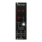
CM1A Controls
Controls
- USB – Connect to a computer to transmit MIDI control signals to the CV and Trig outputs. The module can also receive firmware updates via this connection.
- MIDI IN – Connect a MIDI controller to transmit signals to the CV and Trig outputs.
- MIDI THRU – Pass the signals received at the MIDI In jack to other devices.
- CV – Send control voltages received via USB or MIDI to other modules.
- TRIG – Send trigger signals received via USB or MIDI to other modules.
- TRIG MODE – Selects whether the Trig outputs function as V-trig or S-Trig.
In the middle position, the upper output functions as S-trig and the lower output functions as V-trig.

Mode Select
A button on the rear panel allows the CM1A to be configured for use with various synth families offered by Behringer. The first LED indicates whether the CV range is optimal for System 15/35/55 or System 100/2500 series modules.
The second LED indicates monophonic or duophonic operation.
Press the button quickly to switch the CV range, or press and hold to switch between monophonic and duophonic.
| Mode | LED colors | Operation |
| Mode 1 | Red/red | System 15/35/55 CV range, monophonic |
| Mode 2 | Green/red | System 100/2500 series CV range, monophonic |
| Mode 3 | Red/green | System 15/35/55 CV range, duophonic |
| Mode 4 | Green/green | System 100/2500 series CV range, duophonic |
SYNTHTRIBE
Download the SYNTHTRIBE application from behringer.com to adjust pitch bend range, select MIDI channel and CV mode, and adjust note range (C0 to C9), and other calibration.
Power Connection
The CM1A module comes with the required power cable for connecting to a standard Eurorack power supply system. Follow these steps to connect power to the module. It is easier to make these connections before the module has been mounted into a rack case.
- Turn the power supply or rack case power off and disconnect the power cable.
- Insert the 16-pin connector on the power cable into the socket on the power supply or rack case. The connector has a tab that will align with the gap in the socket, so it cannot be inserted incorrectly. If the power supply does not have a keyed socket, be sure to orient pin 1 (-12 V) with the red stripe on the cable.
- Insert the 10-pin connector into the socket on the back of the module.
The connector has a tab that will align with the socket for correct orientation. - After both ends of the power cable have been securely attached, you may mount the module in a case and turn on the power supply.

Installation
The necessary screws are included with the module for mounting in a Eurorack case. Connect the power cable before mounting.
Depending on the rack case, there may be a series of fixed holes spaced 2 HP apart along the length of the case, or a track that allows individual threaded plates to slide along the length of the case. The free-moving threaded plates allow precise positioning of the module, but each plate should be positioned in the approximate relation to the mounting holes in your module before attaching the screws.
Hold the module against the Eurorack rails so that each of the mounting holes are aligned with a threaded rail or threaded plate. Attach the screws part way to start, which will allow small adjustments to the positioning while you get them all aligned. After the final position has been established, tighten the screws down.
Specifications
| Outputs | |
| CV | |
| Type | 2 x 3.5 mm TS jack, DC coupled |
| Impedance | 100 Ω |
| Max output level | -6.3 V to +10 V |
| CV range, System 100, 2500 series mode | -1 V to +9 V, 1 V/octave |
| CV range, System 15, 35, 55 mode | -5.3 V to +4.7 V, 1 V/octave |
| CV modes | output |
| Trig | |
| Type | 2 x 3.5 mm TS jack, DC coupled |
| Impedance | 25 Ω |
| Max output leve | +5 V when in V-Trig mode, S-Trig = pull down to 0 V |
| Trig modes | V-Trig, S-Trig, both: upper = S-Trig, lower = V-Trig |
| MIDI | |
| Type | 2 x 5-pin DIN |
| MIDI IN and MIDI THRU | |
| MIDI Channel (1 to 16) set via SynthTribe tool | |
| USB | |
| Type | USB 2.0, Type B |
| Mode select (rear panel) | |
| Mode 1, underside LEDs = red/red | System 15, 35, 55 CV range, monophonic |
| Mode 2, underside LEDs = green/red | System 100, 2500 series CV range, monophonic |
| Mode 3, underside LEDs = red/green | System 15, 35, 55 CV range, duophonic |
| Mode 4, underside LEDs = green/green | System 100, 2500 series CV range, duophonic |
| Power | |
| Power supply | Euro rack |
| Current draw | 70 mA (+12 V), 10 mA (-12 V) |
| Physical | |
| Dimensions | 30 x 129 x 520 mm (1.18 x 5.08 x 20.47″) |
| Rack units | 6 HP |
| Weight | 0.09 kg (0.19 lbs) |
FEDERAL COMMUNICATIONS COMMISSION COMPLIANCE INFORMATION
CM1A
This equipment has been tested and found to comply with the limits for a Class B digital device, pursuant to part 15 of the FCC Rules. These limits are designed to provide reasonable protection against harmful interference in a residential installation. This equipment generates, uses and can radiate radio frequency energy and, if not installed and used in accordance with the instructions, may cause harmful interference to radio communications. However, there is no guarantee that interference will not occur in a particular installation. If this equipment does cause harmful interference to radio or television reception, which can be determined by turning the equipment off and on, the user is encouraged to try to correct the interference by one or more of the following measures:
- Reorient or relocate the receiving antenna.
- Increase the separation between the equipment and receiver.
- Connect the equipment into an outlet on a circuit different from that to which the receiver is connected.
- Consult the dealer or an experienced radio/TV technician for help.
This equipment complies with Part 15 of the FCC rules. Operation is subject to the following two conditions:
- this device may not cause harmful interference, and
- this device must accept any interference received, including interference that may cause undesired operation.
Important information:
Changes or modifications to the equipment not expressly approved by Music Tribe can void the user’s authority to use the equipment.
![]() Hereby, Music Tribe declares that this product is in compliance with General Product Safety Regulation (EU) 2023/988, Directive 2014/30/EU, Directive 2011/65/EU and Amendment 2015/863/EU, Directive 2012/19/EU, Regulation 519/2012 REACH SVHC and Directive 1907/2006/EC.
Hereby, Music Tribe declares that this product is in compliance with General Product Safety Regulation (EU) 2023/988, Directive 2014/30/EU, Directive 2011/65/EU and Amendment 2015/863/EU, Directive 2012/19/EU, Regulation 519/2012 REACH SVHC and Directive 1907/2006/EC.
Full text of EU DoC is available at https://community.musictribe.com/
EU Representative: Music Tribe Brands DK A/S
Address: Gammel Strand 44, DK-1202 København K, Denmark
UK Representative: Music Tribe Brands UK Ltd.
Address: 8th Floor, 20 Farringdon Street London EC4A 4AB, United Kingdom
![]() Correct disposal of this product: This symbol indicates that this product must not be disposed of with household waste, according to the WEEE Directive (2012/19/EU) and your national law. This product should be taken to a collection center licensed for the recycling of waste electrical and electronic equipment (EEE). The mishandling of this type of waste could have a possible negative impact on the environment and human health due to potentially hazardous substances that are generally associated with EEE. At the same time, your cooperation in the correct disposal of this product will contribute to the efficient use of natural resources. For more information about where you can take your waste equipment for recycling, please contact your local city office, or your household waste collection service.
Correct disposal of this product: This symbol indicates that this product must not be disposed of with household waste, according to the WEEE Directive (2012/19/EU) and your national law. This product should be taken to a collection center licensed for the recycling of waste electrical and electronic equipment (EEE). The mishandling of this type of waste could have a possible negative impact on the environment and human health due to potentially hazardous substances that are generally associated with EEE. At the same time, your cooperation in the correct disposal of this product will contribute to the efficient use of natural resources. For more information about where you can take your waste equipment for recycling, please contact your local city office, or your household waste collection service.
CUSTOMER SUPPORT
Responsible Party Name: Music Tribe Commercial NV Inc.
Address: 122 E. 42nd St.1,
8th Floor NY, NY 10168,
United States
Email Address: legal@musictribe.com
Documents / Resources
 |
behringer CM1A High Resolution 16 Bit MIDI to CV Converter Module for Eurorack [pdf] User Guide CM1A High Resolution 16 Bit MIDI to CV Converter Module for Eurorack, CM1A, High Resolution 16 Bit MIDI to CV Converter Module for Eurorack, Resolution 16 Bit MIDI to CV Converter Module for Eurorack, Converter Module for Eurorack, Module for Eurorack |