behringer 961 INTERFACE Legendary Analog Multi Channel Trigger Converter Module for Eurorack
Quick Start Guide
961 INTERFACE
Legendary Analog Multi-Channel Trigger Converter Module for Eurorack
Safety Instruction
- Please read and follow all instructions.
- Keep the apparatus away from water, except for outdoor products..
- Clean only with a dry cloth.
- Do not block any ventilation openings. Install in accordance with the manufacturer’s instructions.
- Do not install near any heat sources such as radiators, heat registers, stoves or other apparatus (including amplifiers) that produce heat.
- Use only attachments/accessories specified by the manufacturer.
- Use only specified carts, stands, tripods, brackets, or tables. Use caution to prevent tip-over when moving the cart/apparatus combination.
 Avoid installing in confined spaces like bookcases.
- Do not place near naked flame sources, such as lighted candles.
- Operating temperature range 5° to 45°C (41° to 113°F).
LEGAL DISCLAIMER
Music Tribe accepts no liability for any loss which may be suffered by any person who relies either wholly or in part upon any description, photograph, or statement contained herein. Technical specifications, appearances and other information are subject to change without notice. All trademarks are the property of their respective owners. Midas, Klark Teknik, Lab Gruppen, Lake, Tannoy, Turbosound, TC Electronic, TC Helicon, Behringer, Bugera, Aston Microphones and Coolaudio are trademarks or registered trademarks of Music Tribe Global Brands Ltd. © Music Tribe Global Brands Ltd. 2024 All rights reserved.
LIMITED WARRANTY
For the applicable warranty terms and conditions and additional information regarding Music Tribe’s Limited Warranty, please see complete details online at community. musictribe.com/support.
961 INTERFACE Controls
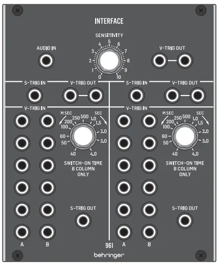
Controls
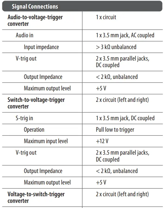
- AUDIO IN – Use this 3.5 mm jack to route an audio signal into the module for conversion to a V-Trig (voltage trigger) signal. The audio signal passes through the SENSITIVITY control before being converted, and the final, converted signal then exits the module at the V-TRIG OUT parallel connections immediately to the right of the SENSITIVITY knob.
- SENSITIVITY – Use this knob to adjust the gain of the audio signal coming into the module through the AUDIO IN jack. Rotate the knob until you find a setting that gives you the best audio-to-voltage conversion.
- V-TRIG OUT – Use the parallel jacks to route the converted audio-to-voltage V-Trig signal back out of the module via cables with 3.5 mm TS connectors.
- S-TRIG IN – Route S-Trig (switch trigger) control signals into the module via cables with 3.5 mm TS connectors for conversion to V-Trig (voltage trigger) signals. The converted V-Trig signal comes back out of the module via the parallel V-TRIG OUT jacks immediately to the right of the S-TRIG IN jack.
- V-TRIG OUT – Use these parallel jacks to send the converted V-Trig signal back out of the module via cables with 3.5 mm TS connectors.
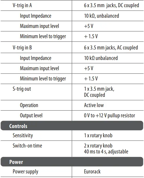
- V-TRIG IN A/B – Use these rows of 3.5 mm jacks to route in multiple V-Trig (voltage trigger) signals for conversion to an S-Trig (switch trigger) signal that exits the module via the S-TRIG OUT jack assigned to this section of the module. The V-TRIG IN A row of inputs go straight to conversion and output, while the V-TRIG IN B row of inputs pass through the SWITCH-ON TIME control before being combined with the converted A signal for final output through the S-TRIG OUT jack. When any valid V-TRIG input activates the S-TRIG output, any other V-TRIG input activity will be ignored until the first V-TRIG cycle has ended.
- SWITCH-ON TIME – Use this knob to manually limit or extend the “ON” time duration of V-Trig signals coming in through the V-TRIG IN B row of input jacks. The “ON” time can be varied from 40 milliseconds to a full 4 seconds.
- S-TRIG OUT – This jack routes the final S-Trig signal from the V-TRIG IN A/B jacks back out of the module via cables with 3.5 mm TS connectors.

Power Connection
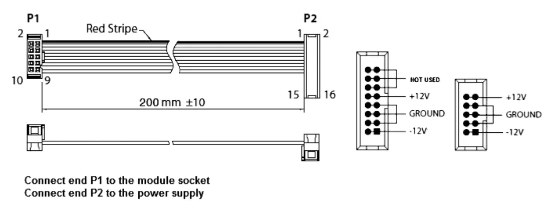
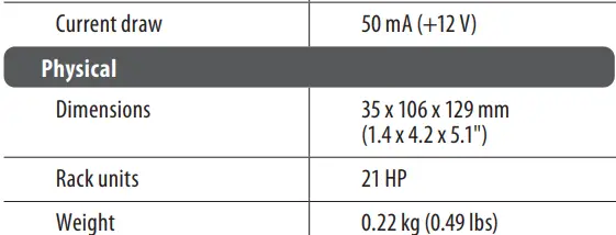
The 961 INTERFACE module comes with the required power cable for connecting to a standard Eurorack power supply system. Follow these steps to connect power to the module. It is easier to make these connections before the module has been mounted into a rack case.
- Turn the power supply or rack case power off and disconnect the power cable.
- Insert the 16-pin connector on the power cable into the socket on the power supply or rack case. The connector has a tab that will align with the gap in the socket, so it cannot be inserted incorrectly. If the power supply does not have a keyed socket, be sure to orient pin 1 (-12 V) with the red stripe on the cable.
- Insert the 10-pin connector into the socket on the back of the module. The connector has a tab that will align with the socket for correct orientation.
- After both ends of the power cable have been securely attached, you may mount the module in a case and turn on the power supply.
Installation
The necessary screws are included with the module for mounting in a Eurorack case. Connect the power cable before mounting.
Depending on the rack case, there may be a series of fixed holes spaced 2 HP apart along the length of the case, or a track that allows individual threaded plates to slide along the length of the case. The free-moving threaded plates allow precise positioning of the module, but each plate should be positioned in the approximate relation to the mounting holes in your module before attaching the screws.
Hold the module against the Eurorack rails so that each of the mounting holes are aligned with a threaded rail or threaded plate. Attach the screws part way to start, which will allow small adjustments to the positioning while you get them
all aligned. After the final position has been established, tighten the screws down.
Specifications
FEDERAL COMMUNICATIONS COMMISSION COMPLIANCE INFORMATION
Behringer
961 INTERFACE
- Responsible Party Name: Music Tribe Commercial NV Inc.
- Address: 122 E. 42nd St.1,
- 8th Floor NY, NY 10168,
- United States
- Email Address: legal@musictribe.com
961 INTERFACE
This equipment has been tested and found to comply with the limits for a Class B digital device, pursuant to part 15 of the FCC Rules. These limits are designed to provide reasonable protection against harmful interference in a residential installation. This equipment generates, uses and can radiate radio frequency energy and, if not installed and used in accordance with the instructions, may cause harmful interference to radio communications. However, there is no guarantee that interference will not occur in a particular installation. If this equipment does cause harmful interference to radio or television reception, which can be determined by turning the equipment off and on, the user is encouraged to try to correct the interference by one or more of the following measures:
- Reorient or relocate the receiving antenna.
- Increase the separation between the equipment and receiver.
- Connect the equipment into an outlet on a circuit different from that to which the receiver is connected.
- Consult the dealer or an experienced radio/TV technician for help.
This equipment complies with Part 15 of the FCC rules. Operation is subject to the following two conditions:
- This device may not cause harmful interference, and
- This device must accept any interference received, including interference that may cause undesired operation.
Important information
Changes or modifications to the equipment not expressly approved by Music Tribe can void the user’s authority to use the equipment.
![]() Hereby, Music Tribe declares that this product is in compliance with Directive 2014/30/EU, Directive 2011/65/EU and Amendment 2015/863/EU, Directive 2012/19/EU, Regulation 519/2012 REACH SVHC and Directive 1907/2006/EC.
Hereby, Music Tribe declares that this product is in compliance with Directive 2014/30/EU, Directive 2011/65/EU and Amendment 2015/863/EU, Directive 2012/19/EU, Regulation 519/2012 REACH SVHC and Directive 1907/2006/EC.
Full text of EU DoC is available at https://community.musictribe.com/
EU Representative: Music Tribe Brands DK A/S
Address: Gammel Strand 44, DK-1202 København K, Denmark
UK Representative: Music Tribe Brands UK Ltd.
Address: 8th Floor, 20 Farringdon Street London EC4A 4AB, United Kingdom
 Correct disposal of this product: This symbol indicates that this product must not be disposed of with household waste, according to the WEEE Directive (2012/19/EU) and your national law. This product should be taken to a collection center licensed for the recycling of waste electrical and electronic equipment (EEE). The mishandling of this type of waste could have a possible negative impact on the environment and human health due to potentially hazardous substances that are generally associated with EEE. At the same time, your cooperation in the correct disposal of this product will contribute to the efficient use of natural resources. For more information about where you can take your waste equipment for recycling, please contact your local city office, or your household waste collection service.
Documents / Resources
 |
behringer 961 INTERFACE Legendary Analog Multi Channel Trigger Converter Module for Eurorack [pdf] Instruction Manual 961 INTERFACE Legendary Analog Multi Channel Trigger Converter Module for Eurorack, 961 INTERFACE, Legendary Analog Multi Channel Trigger Converter Module for Eurorack, Channel Trigger Converter Module for Eurorack, Trigger Converter Module for Eurorack, Converter Module for Eurorack, Module for Eurorack, Eurorack |