
1. Introduction
Thank you for choosing the KAIWEETS KC200D Digital Clamp Meter. This device is a compact, high-precision instrument designed for electrical measurements in various settings, including home, commercial, and industrial environments. It features True RMS technology for accurate readings of complex waveforms, Non-Contact Voltage (NCV) detection for enhanced safety, and a clear backlit LCD for easy readability. This manual provides essential information for safe and effective use of your clamp meter.
2. Safety Information
To ensure safe operation, please read and understand all safety warnings and operating instructions before using this instrument. Failure to observe these warnings can result in serious injury or death.
- Always adhere to local and national safety codes.
- Do not use the meter if it appears damaged or if the insulation on the test leads is compromised.
- Do not apply more than the rated voltage, as marked on the meter, between terminals or between any terminal and ground. The maximum operating voltage is 600V.
- Use extreme caution when working with voltages above 60V DC or 30V AC RMS. These voltages pose a shock hazard.
- Keep your fingers behind the finger guards on the test leads during use.
- Do not operate the meter in explosive gas, vapor, or dust environments.
- Remove the test leads from the circuit before changing functions.
- Always turn off the power to the circuit under test before connecting or disconnecting the test leads.
- Ensure the battery cover is securely closed before operating the meter.
3. Package Contents
Verify that all items listed below are present and undamaged:
- 1 x KAIWEETS KC200D Digital Clamp Meter
- 1 x User Manual
- 1 x Storage Bag
- 2 x Test Leads (Red and Black)
- 2 x AAA 1.5V Batteries
4. Product Overview
The KAIWEETS KC200D is designed for ease of use and durability. Familiarize yourself with the main components:
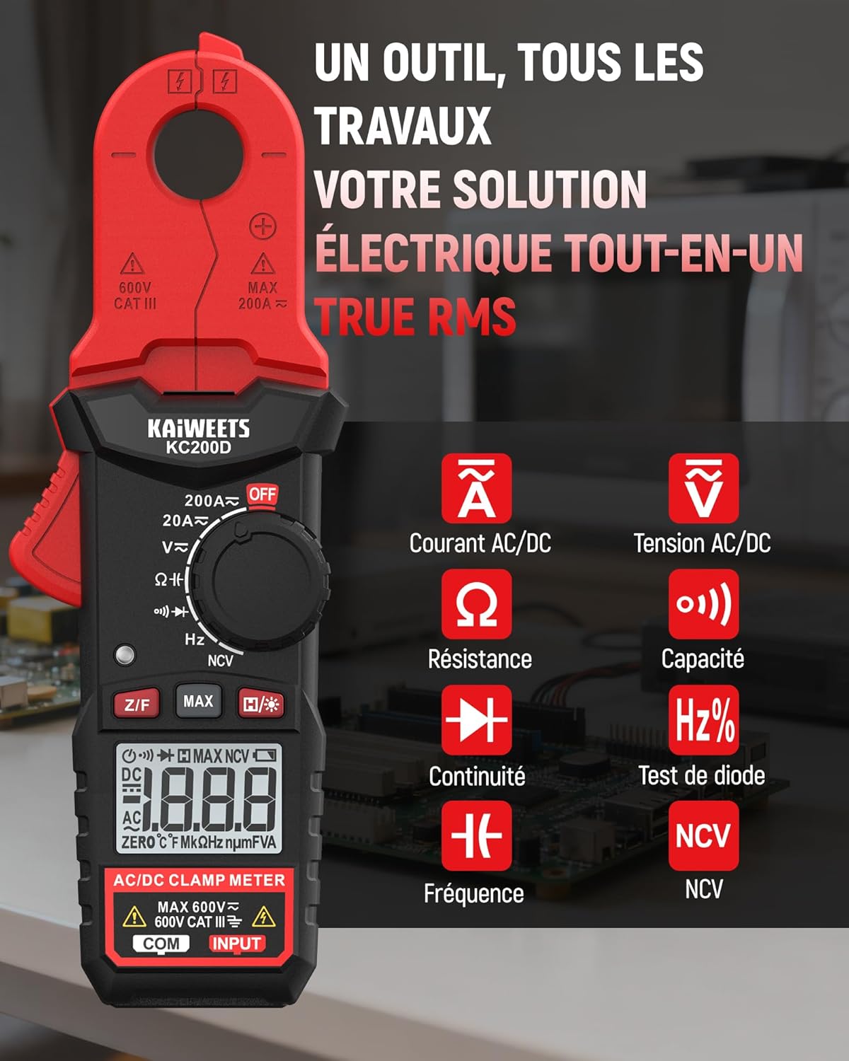
Figure 4.1: KAIWEETS KC200D Clamp Meter with its various measurement functions highlighted, including AC/DC Current, AC/DC Voltage, Resistance, Capacitance, Frequency, Diode Test, Continuity, and NCV.
4.1 Key Components
- Clamp Jaw: Used for non-contact AC/DC current measurement.
- Function Dial: Rotary switch to select measurement modes.
- LCD Display: Shows measurement readings, units, and indicators.
- Buttons: For special functions like Data Hold, MAX/MIN, DC Zero, Backlight, and NCV.
- Input Terminals: For connecting test leads for voltage, resistance, capacitance, frequency, diode, and continuity measurements.
5. Setup
5.1 Battery Installation
The KC200D requires two AAA 1.5V batteries (included).
- Ensure the meter is turned OFF.
- Locate the battery compartment on the back of the meter.
- Use a screwdriver to open the battery compartment cover.
- Insert the two AAA batteries, observing the correct polarity (+ and -).
- Replace the battery compartment cover and secure it with the screw.
5.2 Connecting Test Leads
For measurements requiring test leads (voltage, resistance, capacitance, frequency, diode, continuity):
- Insert the red test lead into the "INPUT" terminal.
- Insert the black test lead into the "COM" (Common) terminal.
6. Operating Instructions
Always select the appropriate function before making any measurement. Turn the function dial to the desired measurement mode.
6.1 AC/DC Current Measurement (Clamp)
Use the clamp jaw for non-contact current measurement. This method is ideal for safely measuring current without breaking the circuit.

Figure 6.1: The clamp jaw of the KC200D measuring current on a single electrical wire, demonstrating its compact design and precision.
- Turn the function dial to the 20A~ or 200A~ position for AC current, or 20A= or 200A= for DC current.
- Press the clamp trigger to open the jaw.
- Encircle only one conductor with the clamp jaw. Do not clamp around multiple wires, as this will result in an inaccurate reading.
- For DC current measurement, press the Z/F button to zero the display before clamping.
- Read the current value on the LCD display.
6.2 AC/DC Voltage Measurement
To measure voltage, use the test leads.
- Turn the function dial to the V~ (AC Voltage) or V= (DC Voltage) position.
- Connect the red test lead to the positive side of the circuit and the black test lead to the negative side (or ground).
- Read the voltage value on the LCD display.
6.3 Resistance Measurement
Ensure the circuit is de-energized before measuring resistance.
- Turn the function dial to the Ω position.
- Connect the test leads across the component to be measured.
- Read the resistance value on the LCD display.
6.4 Capacitance Measurement
Discharge capacitors completely before measurement to avoid damage to the meter or injury.
- Turn the function dial to the Capacitance position (often shared with Diode/Continuity, press FUNC to cycle).
- Connect the test leads across the capacitor.
- Read the capacitance value on the LCD display.
6.5 Frequency Measurement
To measure frequency:
- Turn the function dial to the Hz% position.
- Connect the test leads across the circuit where frequency is to be measured.
- Read the frequency value on the LCD display.
6.6 Diode Test
Ensure the diode is disconnected from the circuit.
- Turn the function dial to the Diode position (often shared with Capacitance/Continuity, press FUNC to cycle).
- Connect the red test lead to the anode and the black test lead to the cathode.
- A forward voltage drop will be displayed for a good diode. Reverse the leads; the display should show OL (Open Loop).
6.7 Continuity Test
Ensure the circuit is de-energized.
- Turn the function dial to the Continuity position (often shared with Diode/Capacitance, press FUNC to cycle).
- Connect the test leads across the component or wire.
- If there is continuity (low resistance), the meter will emit an audible beep.
6.8 Non-Contact Voltage (NCV) Detection
The NCV function allows for quick and safe detection of live AC voltage without direct contact.

Figure 6.2: The KC200D performing Non-Contact Voltage (NCV) detection near an electrical outlet, showing visual indicators for low and high voltage presence.
- Turn the function dial to the NCV position.
- Bring the top end of the meter near the conductor or outlet.
- The meter will emit an audible beep and illuminate LED indicators, with frequency increasing as voltage strength increases.
6.9 Special Functions

Figure 6.3: The KC200D highlighting its user-friendly functions: MAX for peak value, Z/F for DC current zeroing, H for data hold, backlight for low-light conditions, and auto-off for battery saving.
- Data Hold (H/* button): Press to freeze the current reading on the display. Press again to release.
- MAX/MIN (MAX button): Press to display the maximum or minimum measured value. Press again to cycle.
- DC Current Zero (Z/F button): For DC current measurements, press this button before clamping to zero out any residual readings.
- Backlight (H/* long press): Long press the H/* button to turn the display backlight ON or OFF for improved visibility in low-light conditions.
- Auto-Off: The meter automatically powers off after approximately 15 minutes of inactivity to conserve battery life. Press any button or rotate the function dial to wake it up.
7. Maintenance
7.1 Cleaning
Wipe the meter with a dry, soft cloth. Do not use abrasives or solvents.
7.2 Battery Replacement
When the battery indicator appears on the LCD, replace the batteries as described in the Setup section (5.1 Battery Installation).
7.3 Storage
If the meter is not used for an extended period, remove the batteries to prevent leakage and damage. Store the meter in its carrying bag in a cool, dry place.
8. Troubleshooting
| Problem | Possible Cause | Solution |
|---|---|---|
| Meter does not power on | Dead batteries; Incorrect battery installation | Replace batteries; Check battery polarity |
| Inaccurate current reading | Multiple conductors in clamp jaw; DC current not zeroed | Ensure only one conductor is clamped; Press Z/F button for DC current |
| "OL" displayed (Overload) | Measurement exceeds range; Open circuit (for continuity/resistance) | Select a higher range (if available); Check circuit connections |
| No NCV detection | No AC voltage present; Meter not close enough to source | Verify AC voltage presence; Move meter closer to the live conductor |
9. Specifications
Technical specifications for the KAIWEETS KC200D Digital Clamp Meter:
| Feature | Specification |
|---|---|
| Model Number | KC200D |
| Display | 2000 Counts, Backlit LCD |
| AC Current | 20A/200A (±(2.5% + 5 digits)) |
| DC Current | 20A/200A (±(2.5% + 5 digits)) |
| AC Voltage | 2V/20V/200V/600V (±(1.0% + 5 digits)) |
| DC Voltage | 200mV/2V/20V/200V/600V (±(0.5% + 5 digits)) |
| Resistance | 200Ω/2kΩ/20kΩ/200kΩ/2MΩ/20MΩ (±(1.0% + 5 digits)) |
| Capacitance | 2nF/20nF/200nF/2µF/20µF/200µF/2mF/20mF (±(4.0% + 5 digits)) |
| Frequency | 2Hz/20Hz/200Hz/2kHz/20kHz/200kHz/2MHz/20MHz (±(1.0% + 3 digits)) |
| Diode Test | Yes |
| Continuity Test | Yes |
| NCV Detection | Yes |
| Power Supply | 2 x AAA 1.5V Batteries |
| Safety Rating | CAT III 600V, Pollution Level: 2 |
| Dimensions | 20.7 x 11.3 x 4.7 cm (Package) |
| Weight | 308 grams (Package) |
10. Warranty and Support
KAIWEETS products are designed for reliability and performance. For warranty information, technical support, or service inquiries, please refer to the contact information provided on the KAIWEETS official website or contact your local distributor. Please retain your purchase receipt as proof of purchase for warranty claims.


