
1. Product Overview
The darkFlash FLOATRON F1 is a Micro-ATX PC case designed for compact yet powerful computer builds. It features a 270-degree panoramic glass view, a floating design, and support for back-connect motherboards. This case includes three pre-installed ARGB PWM fans for efficient cooling and customizable lighting. Its optimized internal layout facilitates easy assembly and cable management, supporting various high-performance components.

Image 1.1: The darkFlash FLOATRON F1 PC Case showcasing its panoramic glass panels and internal components with blue RGB illumination.
Video 1.1: An overview of the darkFlash FLOATRON F1 PC Case, highlighting its design and features.
2. Package Contents
Verify that all components are present in the package before beginning assembly:
- darkFlash FLOATRON F1 Micro-ATX PC Case
- 3x darkFlash DM08 ARGB PWM Fans (pre-installed)
- Accessory box containing mounting screws, cable ties, and additional tabs
- User Manual (this document)
3. Specifications
| Feature | Specification |
|---|---|
| Model Name | FLOATRON F1 |
| Case Type | Midi Tower (Micro-ATX) |
| Motherboard Compatibility | Micro ATX, ITX (supports back-connect layouts) |
| Dimensions (LxWxH) | 15 x 9 x 18.1 inches (381 x 228.6 x 459.74 mm) |
| Item Weight | 11.57 pounds (5.26 kg) |
| Material | Metal, Tempered Glass |
| GPU Clearance | Up to 350mm (Max 425mm, refer to Image 3.1) |
| CPU Cooler Height | Up to 185mm |
| AIO Radiator Support | Up to 360mm |
| Pre-installed Fans | 3x 120mm ARGB PWM (2x Side, 1x Rear) |
| I/O Ports | 1x Type-C, 2x USB 3.0, HD Audio, Reset, Power |
| Drive Bays | Multiple HDD/SSD mounts (3.5" internal x3 Max, 2.5" internal x3 Max) |
| PSU Mounting Type | Bottom Mount |
| Cooling Method | Air, Water |
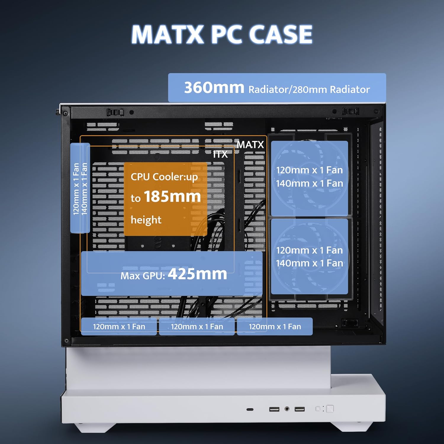
Image 3.1: Diagram illustrating the maximum component clearances for GPU, CPU cooler, and radiator sizes within the FLOATRON F1 case.
4. Setup Guide
4.1 Preparing the Case
- Unpacking: Carefully remove the case from its packaging. Inspect for any damage during transit.
- Panel Removal: The FLOATRON F1 features tool-free side and front panels. Gently pull the panels to detach them for access to the interior. The top panel is secured by two knurled screws; unscrew these to remove the top panel.

Image 4.1: Exploded view of the darkFlash FLOATRON F1 case demonstrating the easy removal of panels for installation and maintenance.
4.2 Motherboard Installation
- Standoffs: Ensure the correct motherboard standoffs are installed for your Micro-ATX or ITX motherboard.
- Mounting: Carefully align your motherboard with the standoffs and I/O shield opening. Secure the motherboard with the provided screws.
- Back-Connect Support: If using a back-connect motherboard, route all necessary cables through the designated cutouts behind the motherboard tray for a cleaner aesthetic and improved airflow.

Image 4.2: Internal view of the darkFlash FLOATRON F1 highlighting the design for back-connect motherboard support, which aids in cable management.
4.3 Power Supply Unit (PSU) Installation
- Location: The PSU is installed in the bottom compartment of the case.
- Mounting: Slide the PSU into its designated slot and secure it with screws from the rear of the case.
- Cable Management: Route PSU cables through the cutouts to the main compartment. Utilize the ample space in the bottom compartment for excess cable length to maintain a tidy build.

Image 4.3: Diagram illustrating the optimized internal layout and the bottom-mounted power supply unit (PSU) placement for efficient space utilization.
4.4 Component Installation (GPU, Storage, Cooling)
- GPU: Install your graphics card into the PCIe slot. Ensure it is securely fastened. The case supports GPUs up to 350mm (or 425mm depending on fan configuration).
- Storage: Mount 3.5-inch HDDs in the bottom compartment and 2.5-inch SSDs behind the motherboard tray using the provided rails and screws.
- Cooling: The case supports CPU coolers up to 185mm in height and AIO liquid coolers up to 360mm. Install additional fans as desired for optimal airflow.

Image 4.4: An internal view of the darkFlash FLOATRON F1 case, showing the spacious interior for various components like the GPU, CPU cooler, and storage drives.
Video 4.1: A detailed video guide demonstrating the assembly process for components within the darkFlash FLOATRON F1 PC Case.
5. Operating Instructions
5.1 Powering On
After all components are installed and cables are connected, press the power button located on the front I/O panel to start your system.
5.2 I/O Port Usage
The front I/O panel provides convenient access to essential ports:
- USB Type-C: For high-speed data transfer and connecting modern peripherals.
- USB 3.0 (x2): For connecting USB devices.
- HD Audio: For headphones and microphones.
- Reset Button: To restart the system.

Image 5.1: Close-up view of the front I/O panel on the darkFlash FLOATRON F1, detailing the Type-C, USB 3.0, HD Audio, Reset, and Power buttons.
5.3 ARGB Fan Control
The pre-installed darkFlash DM08 ARGB PWM fans support motherboard ARGB sync. Connect the fan RGB cables to your motherboard's 5V ARGB header. Use your motherboard's software to customize lighting effects and synchronize them with other compatible components.
6. Maintenance
6.1 Dust Filter Cleaning
The case features magnetic dust filters for easy removal and cleaning. Regularly check and clean these filters to maintain optimal airflow and prevent dust buildup inside the case. Simply detach the magnetic filters, clean them with water or compressed air, and reattach once dry.

Image 6.1: Illustration of the darkFlash FLOATRON F1's side and rear panels, highlighting the large mesh vents and magnetic dust filters for optimal heat dissipation and easy maintenance.
6.2 General Cleaning
Use a soft, dry cloth to wipe down the exterior of the case, including the tempered glass panels. For stubborn smudges on glass, a mild glass cleaner can be used sparingly on the cloth, not directly on the glass. Avoid abrasive cleaners or solvents.
7. Troubleshooting
- System Not Powering On:
- Ensure all power cables (24-pin ATX, CPU, GPU, etc.) are securely connected to the motherboard and components.
- Verify the PSU switch is in the 'ON' position.
- Check front panel header connections to the motherboard (Power SW, Reset SW).
- Fans Not Spinning / RGB Not Lighting Up:
- Confirm fan power cables (PWM) are connected to appropriate headers on the motherboard.
- Verify ARGB cables are connected to a 5V ARGB header (not 12V RGB) on the motherboard.
- Check motherboard software for fan speed and RGB control settings.
- No Display Output:
- Ensure the monitor cable is connected to the graphics card, not the motherboard (unless using integrated graphics).
- Reseat the graphics card and RAM modules.
8. Warranty and Support
darkFlash products are covered by a limited warranty. For specific warranty terms and conditions, please refer to the warranty card included with your product or visit the official darkFlash website. If you encounter any issues or require technical assistance, please contact darkFlash customer support through their official channels. Keep your proof of purchase for warranty claims.
Online Resources:
- Official darkFlash Website: www.darkflash.com
- Customer Support Email: Refer to the official website for contact information.


