1. Introduction
This manual provides detailed instructions for the installation, configuration, and troubleshooting of the MACHINIST B450 AM4-K Motherboard. This motherboard is designed to support AMD Ryzen 1st through 5th generation processors and features a Micro-ATX form factor.

Image 1.1: The MACHINIST B450 AM4-K Motherboard with its retail packaging.
2. Setup and Installation
2.1 Motherboard Layout

Image 2.1: Overview of the B450 AM4-K motherboard layout, indicating key connectors and slots.
Refer to Image 2.1 for the location of various components and connectors on the motherboard. Key areas include the CPU socket, DDR4 memory slots, PCIe slots, NVMe M.2 slots, SATA ports, and I/O panel connectors.
2.2 CPU Installation
The MACHINIST B450 AM4-K Motherboard features an AMD AM4 Socket, compatible with AMD Ryzen 1st through 5th generation processors.
- Ensure the CPU socket lever is in the open position.
- Carefully align the triangular mark on your AMD Ryzen processor with the corresponding mark on the AM4 socket.
- Gently place the CPU into the socket without applying force. If it does not seat correctly, re-check alignment.
- Lower the socket lever to secure the CPU in place.

Image 2.2: The AMD AM4 socket, designed for Ryzen 1st-5th generation processors.
2.3 Memory Installation
The motherboard supports dual-channel DDR4 memory with two slots, allowing for a maximum capacity of 128GB (32GB x 4). Effective frequencies up to 3600MHz are supported.
- Open the clips at both ends of the DDR4 memory slots.
- Align the notch on the memory module with the key in the DIMM slot.
- Press down firmly on both ends of the memory module until the clips snap into place.
- If installing two memory modules, install them in the black slots for optimal dual-channel performance.
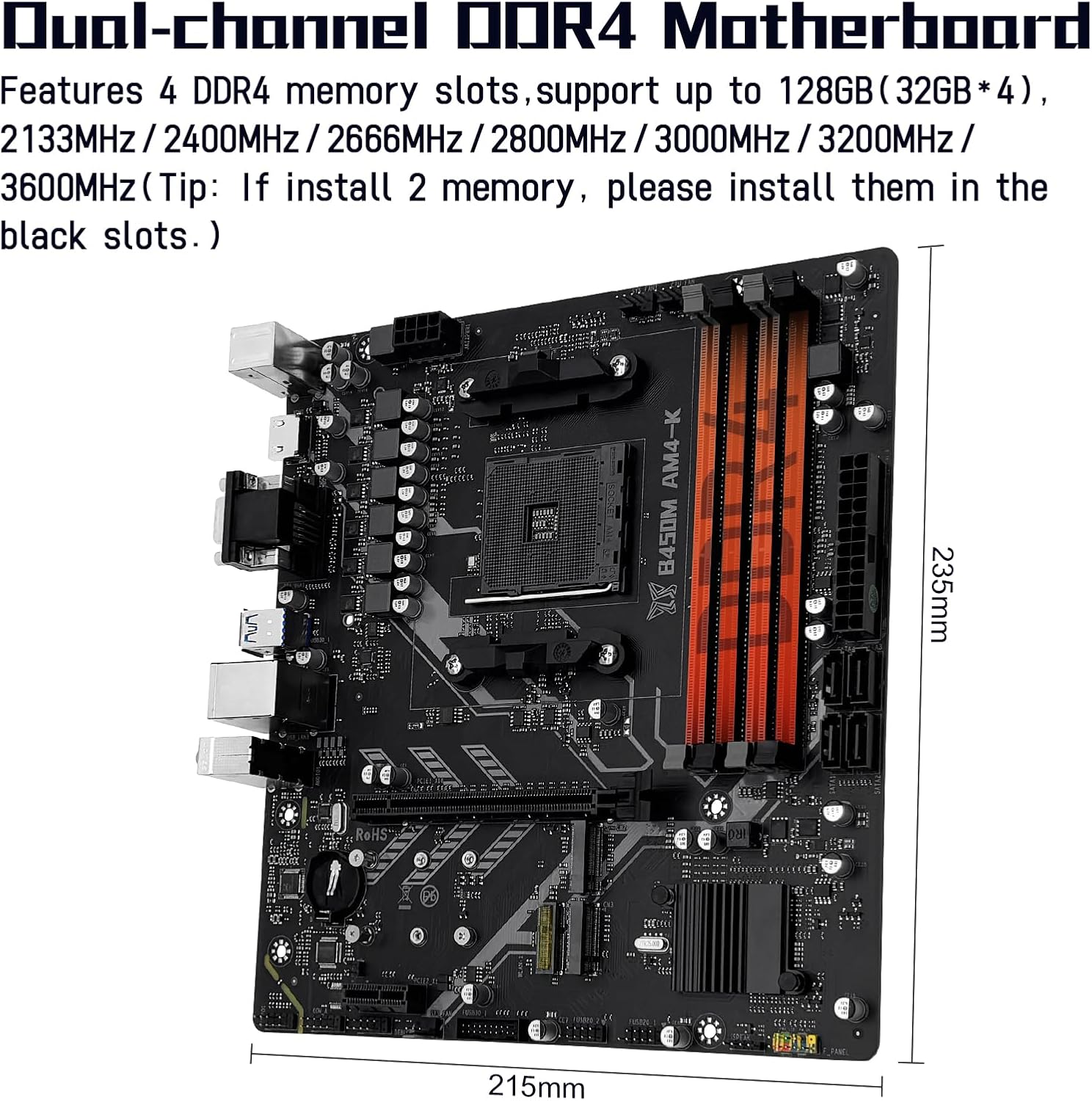
Image 2.3: The dual-channel DDR4 memory slots, supporting up to 128GB.
2.4 Storage Installation
The motherboard includes two NVMe M.2 slots and four SATA 3.0 ports.
2.4.1 NVMe M.2 SSD Installation
One NVMe M.2 slot supports PCIe 3.0 x4 bandwidth, and the other supports PCIe 2.0 x4 bandwidth. There is also a Wi-Fi M.2 slot (NGFF protocol) for wireless network cards, which does not support the CNVI protocol.
- Locate the M.2 slots on the motherboard.
- Remove the M.2 standoff screw.
- Insert the M.2 SSD into the slot at a 30-degree angle.
- Gently push the SSD down and secure it with the standoff screw.
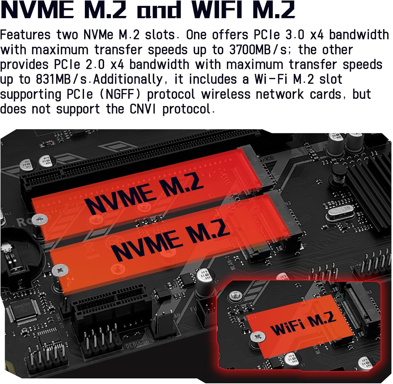
Image 2.4: The NVMe M.2 slots and the dedicated Wi-Fi M.2 slot.
2.4.2 SATA Device Installation
Connect SATA storage devices (HDDs, SSDs) to the SATA 3.0 ports using SATA data cables. Ensure power cables from your power supply are also connected to these devices.
2.5 Expansion Card Installation
The motherboard is equipped with one PCIe 3.0 x16 slot and one PCIe 2.0 x1 slot.
- Align your expansion card (e.g., graphics card in the PCIe 3.0 x16 slot) with the chosen slot.
- Press down firmly until the card is fully seated and the retention clip engages.
- Secure the card to your PC case with a screw.

Image 2.5: The PCIe 3.0 x16 and PCIe 2.0 x1 expansion slots.
2.6 Power Connections
Connect the 24-pin ATX power connector and the 8-pin CPU power connector from your power supply to the corresponding ports on the motherboard. Ensure all connections are secure.
2.7 Front Panel Connections
Connect your PC case's front panel cables (power button, reset button, HDD LED, power LED, USB ports, audio jacks) to the corresponding headers on the motherboard as indicated in Image 2.1.
3. Operating Instructions
3.1 Initial Boot and BIOS/UEFI Access
After completing all hardware installations, connect your monitor, keyboard, and mouse. Power on your system. To access the BIOS/UEFI setup, repeatedly press the designated key (commonly DEL or F2) during the initial boot sequence.
3.2 Driver Installation
For optimal performance and stability, it is recommended to install the latest drivers for your motherboard components. Drivers can typically be found on the manufacturer's website. Alternatively, tools like 'Driver Talent' or using the built-in driver management of Windows 10 can assist with driver installation.
3.3 Video Output Configuration
The motherboard features DisplayPort (DP), VGA, and HDMI-compatible interfaces, supporting 1080P high-definition video output without a dedicated graphics card. Note: To utilize these integrated video outputs, your CPU must support integrated graphics (e.g., AMD Ryzen G-series processors).

Image 3.1: Available video output interfaces: HDMI, VGA, and DisplayPort.
4. Maintenance
Regular maintenance helps ensure the longevity and stable operation of your motherboard.
- Dust Removal: Periodically clean dust from the motherboard and components using compressed air. Ensure the system is powered off and unplugged before cleaning.
- BIOS Updates: Check the manufacturer's website for BIOS/UEFI updates. Updates can improve compatibility, stability, and performance. Follow the update instructions carefully to avoid system damage.
- Cable Management: Ensure internal cables are neatly routed to improve airflow and prevent interference.
5. Troubleshooting
This section addresses common issues you might encounter during setup or operation.
5.1 System Power Issues
- No Power, Fans Not Spinning:
Verify the motherboard power (24-pin) and CPU power (8-pin) connections are secure. Confirm CPU and memory module compatibility and ensure memory modules are properly seated. If the issue persists, clear the CMOS.
5.2 No Display Output
- Fans Spin, Keyboard Lights Unresponsive (Caps Lock):
Verify motherboard and CPU power connections. Ensure memory modules are properly seated and confirm CPU/memory model compatibility. If issues persist, clear the CMOS. - Fans Spin, Keyboard Caps Lock Indicator Lights Up:
Verify the monitor is powered on and the display data cable is securely connected. If no external graphics card (GPU) is installed, confirm your CPU supports integrated graphics. If an external GPU is installed, ensure the data cable is connected to its output port. Check the condition of the display cable, GPU, and monitor. If the issue persists, clear the CMOS.
5.3 How to Clear CMOS
Clearing the CMOS can resolve various boot and configuration issues by resetting BIOS settings to their default values.
- Disconnect the power supply from the motherboard.
- Locate the CMOS clear jumper (often labeled CLR_CMOS or similar) or the CMOS battery.
- If using a jumper, move the jumper cap from pins 1-2 to pins 2-3 for 5-10 seconds, then return it to the original position. If using the battery, remove the CMOS battery for 5-10 seconds and then reinsert it.
- Reconnect the power supply and attempt to boot the system.

Image 5.1: Visual guide for clearing the CMOS.
6. Specifications
Below are the technical specifications for the MACHINIST B450 AM4-K Motherboard:
| Feature | Specification |
|---|---|
| Brand | MACHINIST |
| Model Name | B450 AM4-K |
| CPU Socket | Socket AM4 |
| Compatible Processors | AMD AM4 socket Ryzen 1-5th gen Processors |
| Chipset Type | AMD B450 |
| RAM Memory Technology | DDR4 |
| Memory Slots | 2 x DDR4 (Dual-channel) |
| Max Memory Capacity | 128GB (32GB*4) |
| Supported Memory Frequencies | Up to 3600MHz |
| PCIe 3.0 x16 Slot | 1 |
| PCIe 2.0 x1 Slot | 1 |
| NVMe M.2 Slots | 2 (1x PCIe 3.0 x4, 1x PCIe 2.0 x4) |
| Wi-Fi M.2 Slot | 1 (NGFF Protocol, no CNVI support) |
| SATA 3.0 Ports | 4 |
| Video Interfaces | DP, VGA, HDMI-Compatible (requires CPU with integrated graphics) |
| LAN | Gigabit LAN |
| Form Factor | M-ATX |
| Item Weight | 1.5 pounds |
| Package Dimensions | 10.8 x 8.8 x 2.2 inches |
7. Warranty and Support
This product is covered by a manufacturer's warranty. For specific warranty terms and conditions, please refer to the documentation provided with your purchase or contact the seller directly. For technical support, please reach out to the MACHINIST customer service or the retailer from whom the product was purchased.
Note: This user manual is provided digitally. A physical copy is not included in the product package.


