
1. Introduction
This manual provides detailed instructions for the installation, operation, and maintenance of the GRYVOZE A1201 Waterproof 2-Inch Digital Turbine Flow Meter. This device is designed for accurate measurement of liquid flow in various applications, including hot water, pools, and fuel systems. Please read this manual thoroughly before use to ensure proper function and longevity of the product.
2. Safety Information
- Ensure the flow meter is installed by qualified personnel in accordance with local codes and regulations.
- Verify that the liquid being measured is compatible with the meter's materials (Aluminum alloy, PPS turbine) to prevent corrosion or damage.
- Do not use this flow meter for drinking water or highly corrosive liquids such as strong acids or alkalis.
- Always depressurize the pipeline before installation or maintenance.
- Observe the flow direction arrow on the meter during installation to ensure correct readings.
- The PCB circuit board is not waterproof. Ensure the battery compartment is sealed properly after battery replacement and avoid direct contact with water.
3. Package Contents
The GRYVOZE A1201 Digital Turbine Flow Meter package includes:
- 1 x GRYVOZE A1201 2-Inch Digital Turbine Flow Meter
- User Manual (this document)
4. Product Features
- IPX8 Waterproof Rating: Sealed aluminum alloy housing suitable for outdoor and wet environments.
- High Accuracy: Provides precise readings with a typical accuracy of ±1%.
- Adjustable 360° Display Panel: The round LCD panel can be rotated and fixed at any angle for optimal viewing.
- Energy-Saving Design: LCD screen automatically turns off after 10 minutes of inactivity, extending battery life to over 1 year. Features a low battery alert.
- Easy Battery Replacement: Batteries can be replaced without removing the flow meter from the pipeline.
- EMI Protection: Designed to prevent false readings caused by electromagnetic interference from nearby pumps or motors.
- Multiple Measurement Modes: Displays instantaneous flow, single cumulative flow, and total cumulative flow.
- Selectable Units: Supports Gallons (GAL), Quarts (QTS), Pints (PTS), Liters (L), and Cubic Meters (m³).
Video: Overview of the GRYVOZE 2-Inch Digital Turbine Flow Meter, highlighting its waterproof design, adjustable display, and various measurement modes.
5. Product Overview and Display
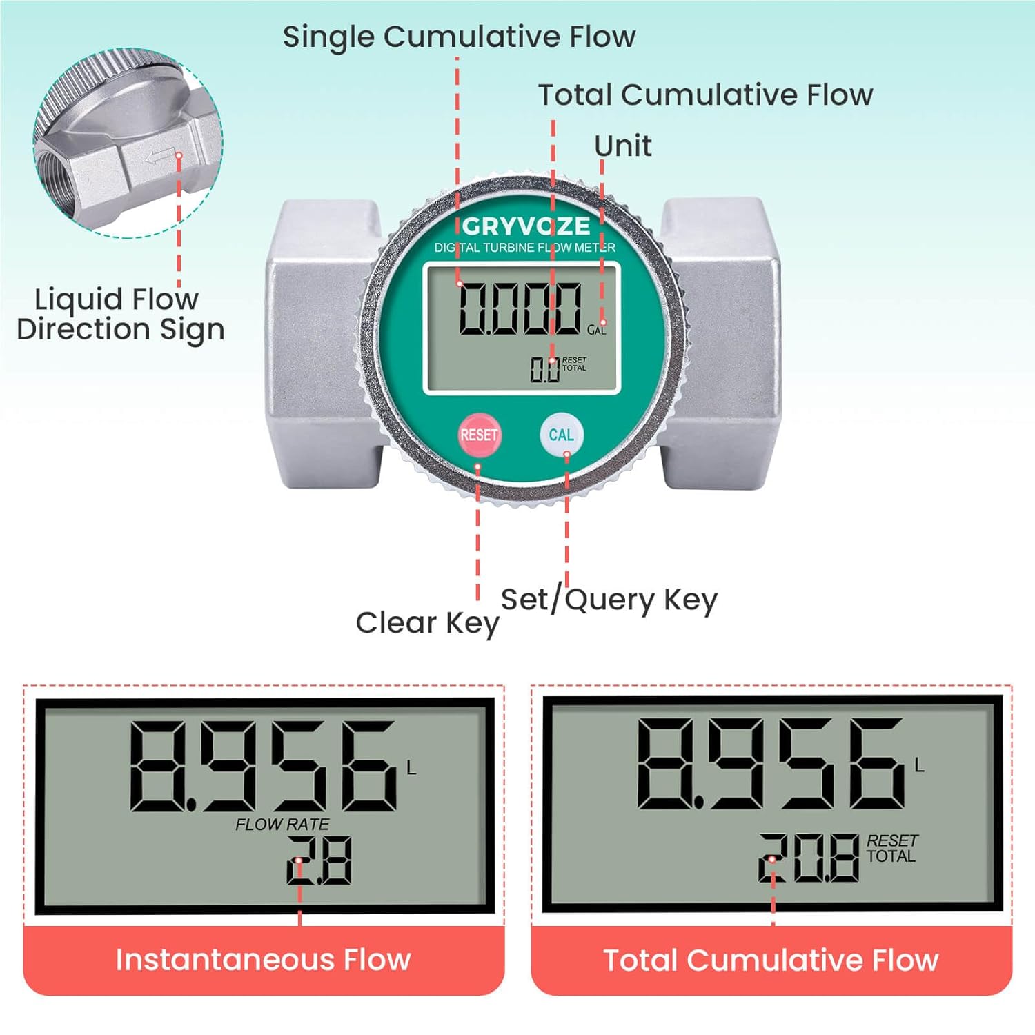
Image: Detailed view of the GRYVOZE flow meter display, indicating the positions of the Single Cumulative Flow, Total Cumulative Flow, Unit, Clear Key, Set/Query Key, and the Liquid Flow Direction Sign. Below are examples of Instantaneous Flow and Total Cumulative Flow readings.
Display Elements:
- Single Cumulative Flow: Resettable flow measurement for a single operation.
- Total Cumulative Flow: Non-resettable total flow measurement.
- Unit: Indicates the current measurement unit (e.g., GAL, L).
- RESET Key: Used to clear the single cumulative flow and enter unit settings.
- CAL Key: Used to query total cumulative flow and save unit settings.

Image: Close-up of the LCD monitor displaying instantaneous flow (top) and single cumulative flow (bottom) readings.
6. Setup and Installation
6.1 Pre-Installation Checks
- Inspect the flow meter for any visible damage.
- Ensure the pipeline is clean and free of debris.
- Confirm the liquid to be measured is within the meter's specified flow range (16-160 GPM) and compatible with its materials.
6.2 Installation Steps
- Depressurize the System: Turn off pumps and close valves to relieve pressure in the pipeline.
- Identify Flow Direction: Locate the arrow on the flow meter body, which indicates the correct direction of liquid flow.
- Thread Connection: The meter features 2-inch NPT female threads. Apply appropriate thread sealant (e.g., PTFE tape) to the male threads of your pipeline.
- Install Meter: Screw the flow meter into the pipeline, ensuring the flow direction arrow aligns with the liquid flow. Tighten securely but do not overtighten.
- Rotate Display (Optional): The display panel can be rotated 360° for optimal viewing after installation. Gently turn the display bezel until it clicks into the desired position.
- Restore Pressure: Slowly open valves and restart pumps to restore pressure to the system. Check for leaks.

Image: Examples of the GRYVOZE flow meter installed in different applications, including industrial pipelines and fuel dispensing nozzles.
6.3 EMI Protection
The GRYVOZE A1201 flow meter is equipped with anti-electromagnetic interference (EMI) functionality. This allows it to be installed in close proximity to pumps or motors without experiencing false readings, which can occur with other flow meters due to magnetic induction.
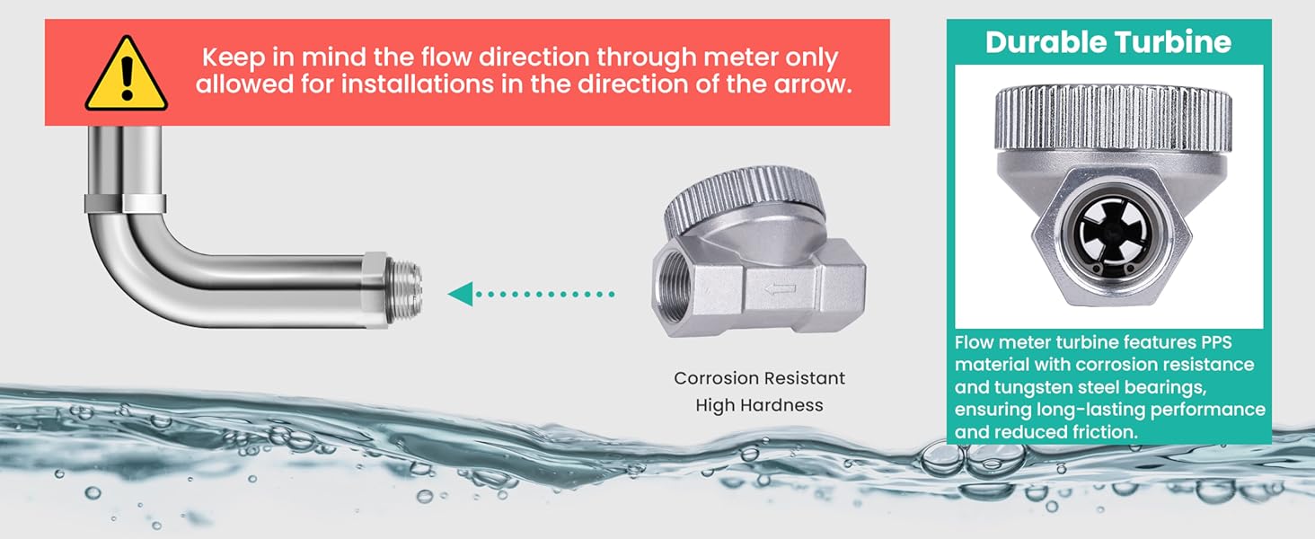
Image: Illustration demonstrating the GRYVOZE flow meter's EMI protection, showing it provides accurate readings even when installed near motors, unlike other meters that may display errors.
7. Operating Instructions
7.1 Power On/Off
- The meter automatically turns on when liquid flows through it.
- It can also be activated by pressing any key.
- The display will automatically turn off after 10 minutes of inactivity to conserve battery power.

Image: Visual representation of the meter's auto-off function after 10 minutes of inactivity and the low battery alert icon on the display.
7.2 Display Modes
The meter displays three types of flow measurements:
- Instantaneous Flow: Shows the current flow rate.
- Single Cumulative Flow: Measures the volume of liquid for a single operation. This value can be reset.
- Total Cumulative Flow: Measures the total volume of liquid passed through the meter since its last factory reset. This value is non-resettable by the user.
7.3 Resetting Single Cumulative Flow
To reset the Single Cumulative Flow, press the RESET key.
7.4 Querying Total Cumulative Flow
To view the Total Cumulative Flow, press the CAL key.
7.5 Changing Measurement Units

Image: Step-by-step guide on how to change the measurement units (GAL, QTS, PTS, L) using the 'C' (CAL) and 'R' (RESET) keys.
- Simultaneously press and hold the CAL and RESET keys for more than 5 seconds to enter the metering unit settings.
- The default metering unit is Liters (L). Press the RESET key to cycle through the available units: Gallons (GAL), Quarts (QTS), Pints (PTS), and Liters (L).
- Once your desired unit is displayed, press and hold the CAL key for 3 seconds to save the setting and exit the unit configuration mode.

Image: Visual representation of the four optional measurement units (GAL, QTS, L, PTS) available for selection on the flow meter.
8. Maintenance
8.1 General Care
- Regularly inspect the meter for any signs of physical damage or leaks.
- Keep the display clean for clear readability. Use a soft, damp cloth. Do not use abrasive cleaners.
8.2 Battery Replacement
The meter uses 2 x AAA LR03 batteries. A low battery alert will appear on the display when replacement is needed.
- Ensure the system is depressurized if possible, though battery replacement can be done without removing the flow meter from the pipeline.
- Carefully unscrew the display panel from the main body of the flow meter.
- Remove the old AAA batteries and insert new ones, observing correct polarity.
- Carefully reattach the display panel, ensuring it is securely screwed back into place to maintain the waterproof seal.

Image: Internal view of the flow meter's PCB circuit board with two AAA batteries, and a separate image of the robust die-cast aluminum housing. Note: The PCB circuit board itself is not waterproof.
9. Troubleshooting
| Problem | Possible Cause | Solution |
|---|---|---|
| No display/Meter not turning on | Dead batteries; No liquid flow; Meter malfunction. | Replace batteries; Ensure liquid is flowing; Contact support if problem persists. |
| Inaccurate readings | Incorrect installation direction; Air in pipeline; Turbine obstruction; Meter malfunction. | Verify flow direction arrow; Purge air from system; Check for debris in turbine; Contact support. |
| Leakage at connections | Improper thread sealant; Loose connection; Damaged threads. | Reapply thread sealant; Tighten connection; Inspect threads for damage. |
| Display shows "Err" or similar error | Internal error; Extreme operating conditions. | Restart meter (remove/reinsert batteries); Ensure operating conditions are within specifications; Contact support. |
10. Specifications
| Feature | Specification |
|---|---|
| Model Number | A1201 |
| Product Dimensions | 12 x 7.5 x 8.5 cm |
| Item Weight | 485 g |
| Material | Aluminum Alloy (housing), PPS (turbine) |
| Thread Type | 2" NPT Female Thread |
| Flow Range | 16-160 GPM (Gallons Per Minute) |
| Accuracy | ±1% |
| Waterproof Rating | IPX8 |
| Display Units | GAL, QTS, PTS, L, m³ |
| Battery Type | 2 x AAA LR03 (included) |
| Battery Life | 1+ year (standby) |
| Applicable Medium | Diesel, gasoline, kerosene, methanol, water, etc. (Not for drinking water, alkaline water, or corrosive liquids) |
| Country of Origin | China |
11. Warranty and Support
GRYVOZE products are manufactured to high-quality standards. For warranty information, technical support, or service inquiries, please refer to the contact information provided with your purchase or visit the official GRYVOZE website. Please retain your proof of purchase for warranty claims.

