
1. Introduction
The ZLLJMETER ZL118 is a portable, smart digital multimeter designed for precise measurement of various electrical parameters. It features a 6000-count LCD display, automatic recognition, and a rechargeable battery, making it suitable for both professionals and hobbyists. This manual provides essential information for safe and effective use of your ZL118 multimeter.
2. Safety Information
Always adhere to safety precautions when using electrical testing equipment to prevent electric shock or personal injury.
- Do not exceed the maximum input values specified for each measurement range.
- Ensure test leads are in good condition, without cracks or damaged insulation.
- Do not use the multimeter if it appears damaged or is not operating correctly.
- Always disconnect power to the circuit under test before connecting or disconnecting test leads, especially when measuring current.
- Be cautious when working with voltages above 30V AC RMS, 42V peak, or 60V DC, as these pose a shock hazard.
- Do not operate the multimeter in explosive gas, vapor, or dusty environments.
- Use the correct function and range for each measurement.
- Keep fingers behind the finger guards on the test probes during measurements.
3. Package Contents
Verify that all items are present in your package:
- 1 x ZLLJMETER ZL118 Digital Multimeter
- 1 x User Manual (this document)
- 1 x Type-C USB Cable
- 1 x Pair of 10A Test Leads
- 1 x Outer Box
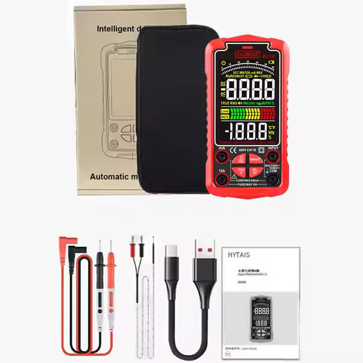
Figure 3.1: Package Contents
4. Product Features and Components
The ZL118 multimeter is designed for ease of use and accuracy. Key features include:
- 6000 Count LCD Display with Backlight
- Automatic Ranging
- True RMS Measurement
- Non-Contact Voltage (NCV) Detection
- Live Wire Test
- Diode Test and Continuity Buzzer
- Data Hold Function
- Flashlight
- Rechargeable Lithium Battery with Type-C USB Charging
- Auto Power Off
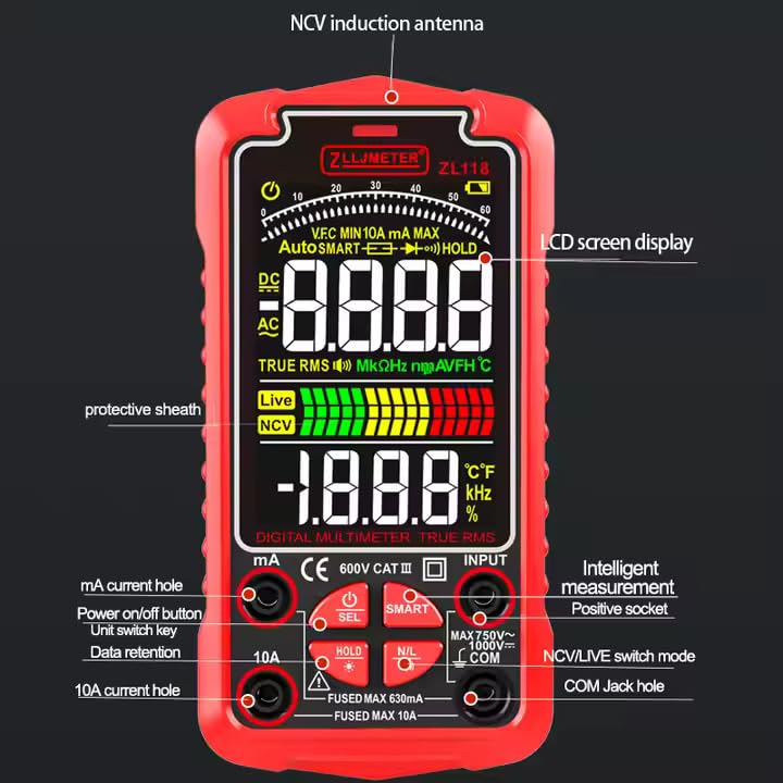
Figure 4.1: ZL118 Multimeter Components

Figure 4.2: Product Screen Display

Figure 4.3: Function Display Icons
5. Setup
5.1 Initial Charging
Before first use, fully charge the multimeter's internal lithium battery using the provided Type-C USB cable. Connect the cable to the multimeter's charging port and a standard USB power source (e.g., computer USB port, USB wall adapter).
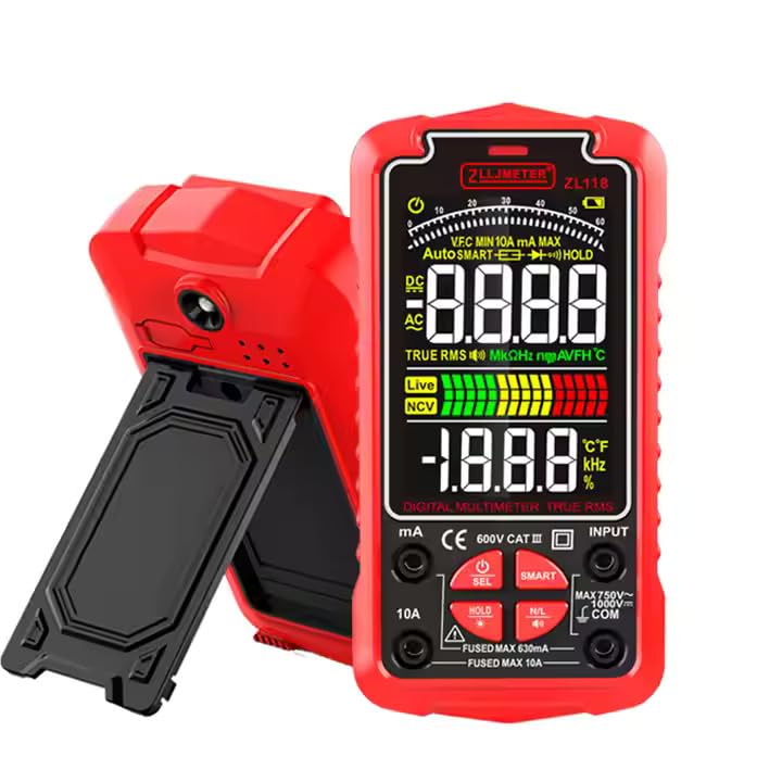
Figure 5.1: USB Type-C Charging
5.2 Connecting Test Leads
Insert the red test lead into the 'VΩmA' or '10A' input jack (depending on the measurement) and the black test lead into the 'COM' (common) input jack. Ensure a secure connection.
6. Operating Instructions
6.1 Power On/Off
Press and hold the power button (⑂) to turn the multimeter on or off. The device will automatically enter auto-ranging mode upon startup.
6.2 Automatic Recognition (SMART Mode)
In SMART mode, the multimeter automatically identifies the measurement type (AC/DC Voltage, Resistance, Continuity) and selects the appropriate range. This is the default mode for general measurements.
6.3 Manual Function Selection
Press the 'FUNC' or 'SEL' button to cycle through different measurement functions if you need to manually select a specific mode not covered by SMART mode, such as Capacitance, Frequency, Diode, NCV, or Live Wire test.
6.4 Measurement Procedures
Voltage Measurement (AC/DC):
- Connect the red test lead to the 'VΩmA' jack and the black lead to 'COM'.
- Select AC or DC Voltage mode (or use SMART mode).
- Connect the test probes in parallel across the circuit or component to be measured.
- Read the voltage value on the display.
Current Measurement (AC/DC):
- Important: Disconnect power to the circuit before connecting the multimeter.
- For mA current, connect the red test lead to the 'VΩmA' jack. For 10A current, connect the red test lead to the '10A' jack. Connect the black lead to 'COM'.
- Select AC or DC Current mode.
- Connect the multimeter in series with the circuit.
- Restore power and read the current value.
Resistance Measurement:
- Ensure the circuit or component is de-energized.
- Connect the red test lead to the 'VΩmA' jack and the black lead to 'COM'.
- Select Resistance mode (or use SMART mode).
- Connect the test probes across the component.
- Read the resistance value.

Figure 6.1: Capacitance, Resistance, and On-Off Measurements
Capacitance Measurement:
- Ensure the capacitor is fully discharged before testing.
- Connect the red test lead to the 'VΩmA' jack and the black lead to 'COM'.
- Select Capacitance mode.
- Connect the test probes across the capacitor.
- Read the capacitance value.
Diode Test:
- Ensure the diode is disconnected from the circuit.
- Connect the red test lead to the 'VΩmA' jack and the black lead to 'COM'.
- Select Diode test mode.
- Connect the red probe to the anode and the black probe to the cathode. A forward voltage drop will be displayed. Reverse the probes; an open circuit (OL) should be displayed for a good diode.
Continuity Test:
- Ensure the circuit is de-energized.
- Connect the red test lead to the 'VΩmA' jack and the black lead to 'COM'.
- Select Continuity mode.
- Touch the probes to the points to be tested. A buzzer will sound if continuity exists (resistance below approximately 50Ω).
NCV (Non-Contact Voltage) Measurement:
- Select NCV mode.
- Bring the top of the multimeter (NCV induction antenna) close to the conductor. The display will show 'EF' and the buzzer will sound with increasing frequency as voltage is detected.
Live Wire Test:
- Connect the red test lead to the 'VΩmA' jack and the black lead to 'COM'.
- Select Live Wire mode.
- Touch the red probe to the live wire. The display will indicate 'LIVE' and the buzzer will sound.

Figure 6.2: Live Line, NCV, and Diode Measurements
6.5 Data Hold
Press the 'HOLD' button to freeze the current reading on the display. Press it again to release the hold function.
6.6 Flashlight
Press the flashlight button (often integrated with 'HOLD' or a separate button) to turn the built-in flashlight on or off for illumination in dark areas.
7. Maintenance
7.1 Cleaning
Wipe the multimeter casing with a damp cloth and mild detergent. Do not use abrasives or solvents. Ensure the device is off and disconnected from any power source before cleaning.
7.2 Battery Charging
Recharge the internal lithium battery when the low battery indicator appears on the display. Use the provided Type-C USB cable and a compatible power adapter. Avoid over-discharging the battery for extended lifespan.
7.3 Storage
Store the multimeter in a cool, dry place, away from direct sunlight and extreme temperatures. If storing for an extended period, ensure the battery is partially charged (around 50%) to prevent deep discharge.
8. Troubleshooting
If you encounter issues with your ZL118 multimeter, refer to the following common problems and solutions:
- No Display/Device Not Turning On:
- Ensure the battery is charged. Connect the multimeter to a USB charger.
- Check if the power button is pressed and held sufficiently.
- Inaccurate Readings:
- Verify that the correct measurement function is selected.
- Ensure test leads are properly connected and not damaged.
- Check if the circuit under test is de-energized for resistance, capacitance, or diode tests.
- For current measurements, ensure the multimeter is connected in series.
- Continuity Buzzer Not Working:
- Ensure Continuity mode is selected.
- Check for proper contact between probes and the circuit.
- 'OL' (Overload) Displayed:
- The measured value exceeds the selected range. The auto-ranging feature should typically handle this, but if in manual mode, switch to a higher range.
- For resistance or continuity, 'OL' can indicate an open circuit.
9. Specifications
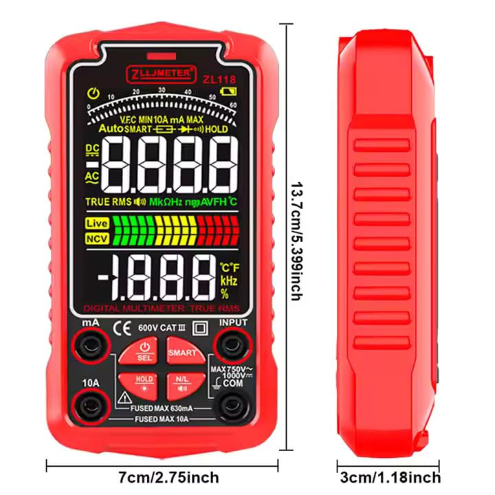
Figure 9.1: Product Dimensions
| Parameter | Range | Accuracy | Resolution |
|---|---|---|---|
| AC Voltage | 60mV/600mV/6V/60V/750V | ±(0.8%+5) | 0.01V |
| DC Voltage | 60mV/600mV/6V/60V/1000V | ±(0.5%+3) | 0.01mV |
| AC Current | 60mA/600mA, 6A/10A | ±(1.2%+8) for mA, ±(2.5%+8) for A | 0.3mA, 0.030A |
| DC Current | 60mA/600mA, 6A/10A | ±(1.0%+8) for mA, ±(2%+8) for A | 0.01mA, 0.001A |
| Resistance | 600Ω/6kΩ/60kΩ/600kΩ/6MΩ/60MΩ | ±(0.8%+3) up to 6MΩ, ±(1.0%+25) for 60MΩ | 0.1Ω |
| Capacitance | 6nF ~ 60mF | ±(4.0%+10) | 1pF |
| Frequency | 10Hz ~ 6MHz | ±(0.1%+5) | 0.01Hz |
| Duty Cycle | 0.1%~99.9% | ±(0.1%+5) | 0.1% |
| Temperature | -40℃~1000℃ | ±(1.5%+5) | 1℃ |
General Specifications:
- Display: 6000 Counts LCD
- Power Source: Rechargeable Lithium Battery
- Dimensions (LxWxH): 13.7 x 7 x 3.2 cm (5.39 x 2.75 x 1.26 inches)
- Item Weight: 400 Grams
- Safety Standard: IEC 61010-1
- Manufacturer: Shenzhen Zhuoliang Laojiang Instrument Co., Ltd.
- Country of Origin: China
10. Warranty
The ZLLJMETER ZL118 Digital Multimeter comes with a 1-Year Warranty from the date of purchase. This warranty covers manufacturing defects and malfunctions under normal use. It does not cover damage caused by misuse, accidents, unauthorized modifications, or improper operation.
11. Support
For technical assistance, warranty claims, or product inquiries, please contact your retailer or the authorized service center. For customers in India, you may contact the importer:
MDS Automech Solutions
Q-106, Phase 3, Shivalik Nagar, BHEL, Haridwar, Uttarakhand-249403
Contact: +91-9870694636
Email: mohit@mdsautomech.in