
1. Introduction
This manual provides detailed instructions for the installation, operation, and maintenance of the Generic SF-205 Digital Display Thermostat. The SF-205 is an electronic temperature controller designed for precise temperature management in display cabinets, refrigerators, and freezers, featuring a digital display and a 30A relay output.
2. Product Overview
The SF-205 is a versatile temperature controller equipped with a clear digital display for real-time temperature monitoring and easy parameter adjustments. It is suitable for various refrigeration applications requiring accurate temperature control.
2.1 Components
- Main Controller Unit: Houses the control circuitry and wiring terminals.
- Digital Display Panel: Front-facing interface with temperature display and control buttons.
- Temperature Sensors: Typically includes a cold-room evaporator sensor and an AC sensor.
- Wiring Harness: Pre-wired connections for various functions.
- Power Transformer (optional/external): For specific voltage requirements.
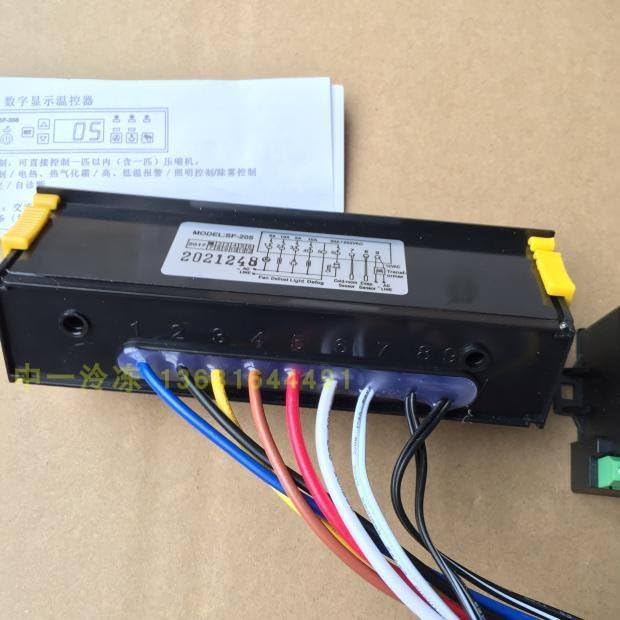
Image: The SF-205 main controller unit with various colored wires connected to its terminals. This view shows the overall physical structure of the device and its primary wiring points.
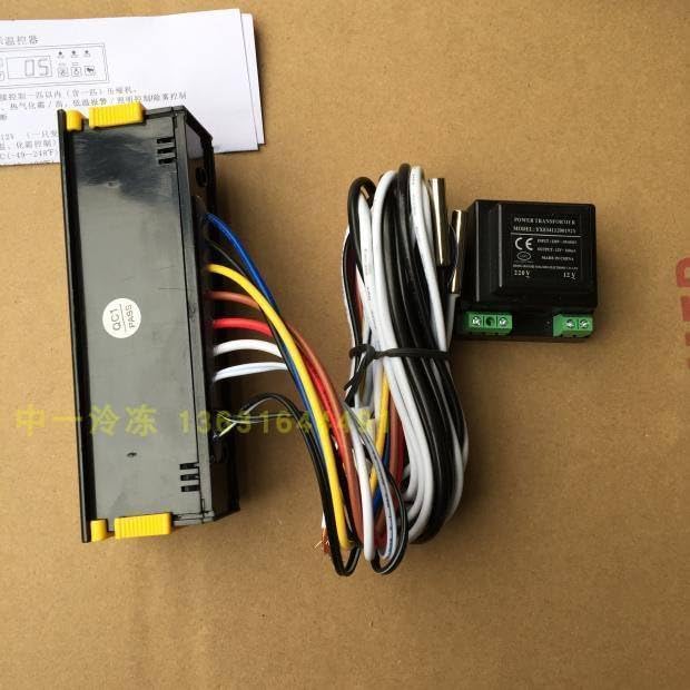
Image: A side view of the SF-205 controller, illustrating the wiring bundle and an external power transformer. This provides a perspective on the complete setup including auxiliary components.
3. Safety Information
WARNING: Electrical installation should only be performed by qualified personnel. Failure to follow these safety instructions may result in electric shock, fire, or damage to the product.
- Always disconnect power before installation, maintenance, or troubleshooting.
- Ensure all wiring connections are secure and comply with local electrical codes.
- Do not operate the device in environments with excessive moisture or extreme temperatures outside its specified operating range.
- Verify the power supply voltage matches the device's requirements.
4. Installation and Wiring
Careful wiring is crucial for the correct and safe operation of the SF-205 thermostat. Refer to the wiring diagram below and ensure all connections are made accurately.
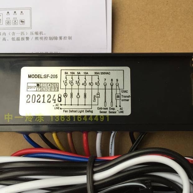
Image: A close-up of the wiring diagram label on the SF-205 unit. This diagram details the terminal connections for power input, sensors, and controlled outputs such as fan, defrost, light, and compressor.
4.1 Wiring Terminals
| Terminal No. | Function | Description |
|---|---|---|
| 1, 2 | AC LINE | Main AC power input. |
| 3 | Fan | Output for controlling the fan. (5A) |
| 4 | Defrost | Output for controlling the defrost heater. (10A) |
| 5 | Light | Output for controlling internal lighting. (10A) |
| 6 | Compressor | Output for controlling the compressor. (30A/250VAC) |
| 7 | Cold-room Evap. Sensor | Input for the cold-room evaporator temperature sensor. |
| 8 | AC Sensor | Input for the ambient AC temperature sensor. |
| 9 | 12VAC Transformer | Output for connecting a 12VAC transformer. |
Note: Ensure proper grounding and insulation for all connections. Consult a professional electrician if you are unsure about any wiring procedures.
5. Operating Instructions
The SF-205 features a user-friendly interface for setting and monitoring temperature. Familiarize yourself with the display and buttons.
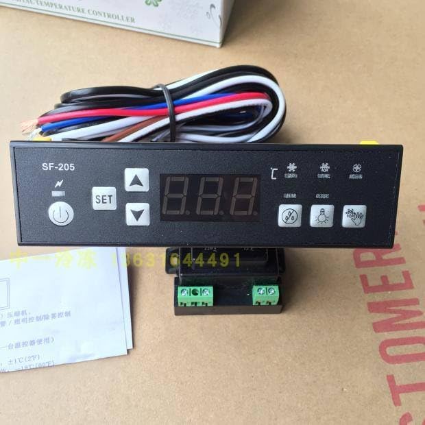
Image: The front panel of the SF-205 thermostat, showing the digital temperature display, power button, SET button, and up/down arrow buttons, along with various indicator icons.
5.1 Display and Buttons
- Digital Display: Shows the current temperature and parameter values.
- ⏻ Power Button: Press to turn the unit on or off.
- SET Button: Used to enter parameter setting mode and confirm selections.
- ▲ Up Button: Increases parameter values or navigates through menu options.
- ▼ Down Button: Decreases parameter values or navigates through menu options.
- Indicator Icons: Various icons may illuminate to indicate compressor status, defrost cycle, fan operation, or alarms.
5.2 Setting the Temperature
- Press the SET button once. The display will show the current set temperature.
- Use the ▲ Up or ▼ Down buttons to adjust the desired temperature.
- Press the SET button again to confirm the new setting and exit. If no button is pressed for a few seconds, the display will revert to showing the current temperature.
5.3 Advanced Parameter Settings
To access advanced parameters (e.g., defrost cycle duration, temperature differential, alarm settings), typically a long press of the SET button or a combination of buttons is required. Refer to the specific parameter codes and their functions, which are usually provided in a separate parameter table (not included in this general manual).
6. Maintenance
Regular maintenance ensures the longevity and optimal performance of your SF-205 thermostat.
- Cleaning: Periodically wipe the display panel and exterior with a soft, dry cloth. Do not use abrasive cleaners or solvents.
- Sensor Check: Ensure temperature sensors are clean and properly positioned. Avoid physical damage to the sensor probes and cables.
- Wiring Inspection: Annually inspect all wiring connections for tightness and signs of wear or corrosion.
7. Troubleshooting
If you encounter issues with your SF-205 thermostat, refer to the following common problems and solutions:
| Problem | Possible Cause | Solution |
|---|---|---|
| Display is blank | No power, loose wiring, faulty unit. | Check power supply. Verify AC LINE connections. If problem persists, contact support. |
| Incorrect temperature reading | Faulty sensor, sensor not properly installed, sensor cable damage. | Check sensor connections. Inspect sensor cable for damage. Replace sensor if necessary. |
| Compressor not turning on/off | Temperature setting issue, faulty compressor relay, wiring error. | Verify set temperature. Check compressor wiring. Consult a technician. |
| Error code displayed | Specific system fault. | Refer to the product's full technical manual for specific error code meanings and troubleshooting steps. |
8. Specifications
- Model: SF-205
- Brand: Generic
- Manufacturer Part Number: ZBTS_NQOD_12774
- Application: Display Cabinet, Refrigerator, Freezer Temperature Control
- Compressor Relay Capacity: 30A / 250VAC
- Defrost Relay Capacity: 10A
- Fan Relay Capacity: 5A
- Light Relay Capacity: 10A
- Power Input: AC (Specific voltage not provided, refer to device label)
- Sensor Type: NTC (Common for such devices, specific type not provided)
- Temperature Control Range: (Specific range not provided, refer to device label or full manual)
9. Warranty and Support
Specific warranty terms and direct support contact information are not provided within the available product details. For warranty claims or technical assistance, please refer to the retailer or vendor from whom the product was purchased.