
GeekLJT LYSP-4AS
Upgraded RDA5807 Radio Soldering Kit Instruction Manual
Model: LYSP-4AS
1. Introduction
This manual provides detailed instructions for assembling, operating, and maintaining your GeekLJT Upgraded RDA5807 Radio Soldering Kit. This kit is designed for electronics hobbyists, DIY enthusiasts, and students to learn and practice soldering skills while building a functional portable FM radio.
The finished product is a digital FM radio with good signal reception, housed in a clear acrylic casing, and features a cool appearance. It is an excellent educational project for understanding basic electronic principles and practical soldering techniques.

Image: The fully assembled RDA5807 FM Radio, showcasing its clear acrylic casing, purple PCB, digital display, and telescopic antenna.
2. Components List
Before beginning assembly, verify that all components listed below are present in your kit. Refer to the image for visual identification of parts.

Image: All individual components of the RDA5807 Radio Soldering Kit laid out, including the PCB, acrylic casing parts, speaker, digital display, various resistors, capacitors, ICs, buttons, antenna, and USB cable.
| Component | Description | Quantity |
|---|---|---|
| Main PCB | Purple Printed Circuit Board with component markings | 1 |
| Acrylic Casing Parts | Transparent panels for enclosure | Multiple |
| Digital Display Module | 7-segment display for frequency | 1 |
| Speaker | Small audio output speaker | 1 |
| Telescopic Antenna | Extendable antenna for FM reception | 1 |
| RDA5807 Module | FM radio receiver chip module | 1 |
| Integrated Circuits (ICs) | Various ICs for control and audio amplification | Multiple |
| Resistors | Various resistance values | Assorted |
| Capacitors | Electrolytic and ceramic capacitors | Assorted |
| Diodes/LEDs | Light Emitting Diodes and rectifier diodes | Assorted |
| Buttons/Switches | Push buttons for control, power switch | Multiple |
| 3.5mm Earphone Jack | Audio output jack | 1 |
| USB Power Cable | For powering the device via USB | 1 |
| Battery Holder | For 3x AAA batteries (batteries not included) | 1 |
| Fasteners | Screws and nuts for assembly | Assorted |
3. Setup and Assembly
This section outlines the steps for assembling your RDA5807 Radio Kit. Basic soldering skills and tools (soldering iron, solder, wire cutters, etc.) are required.
3.1. Soldering Components to PCB
- Identify Components: Carefully identify each component using the provided component list and the markings on the PCB.
- Solder Low-Profile Components First: Begin by soldering components that lie flat on the PCB, such as resistors, diodes, and small capacitors. Ensure correct polarity for diodes and electrolytic capacitors.
- Solder IC Sockets (if applicable) or ICs: If your kit includes IC sockets, solder them first. Otherwise, carefully solder the Integrated Circuits, paying close attention to the orientation (notch or dot indicating Pin 1).
- Solder Larger Components: Proceed with soldering larger components like the RDA5807 module, buttons, switches, 3.5mm earphone jack, and the digital display module.
- Connect Speaker and Antenna: Solder the speaker wires to the designated pads and attach the telescopic antenna.
- Solder Power Connectors: Solder the USB power input and battery holder connectors.
- Inspect Solder Joints: After soldering all components, carefully inspect each joint for cold solder joints, bridges, or poor connections. Re-solder as necessary.
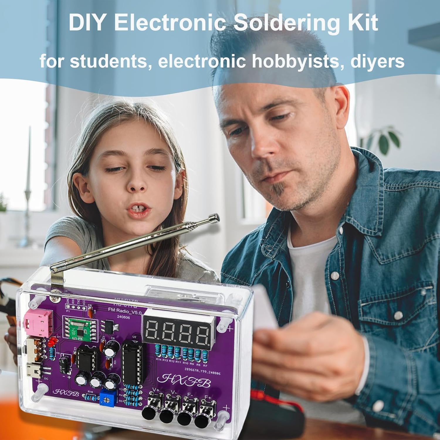
Image: A person and child engaged in soldering the components of the DIY Electronic Soldering Kit, demonstrating the educational aspect of the assembly process.
3.2. Assembling the Acrylic Casing
- Remove Protective Film: Peel off the protective film from both sides of all acrylic casing panels.
- Mount PCB: Carefully align the soldered PCB with the standoffs on the bottom acrylic panel. Secure it with the provided screws.
- Assemble Side Panels: Attach the side panels, ensuring that all ports (USB, earphone jack) and buttons align with their respective cutouts.
- Attach Top Panel: Place the top acrylic panel, ensuring the antenna and display fit through their openings.
- Secure with Fasteners: Use the remaining screws and nuts to firmly secure the entire casing. Do not overtighten.

Image: The finished RDA5807 radio, highlighting its portable size and the 3.5mm earphone jack for connecting headphones or external speakers.
4. Operating Instructions
4.1. Powering the Radio
The radio can be powered by two methods:
- USB Cable: Connect the provided USB cable to the radio's USB port and a 5V USB power source (e.g., computer USB port, USB wall adapter).
- AAA Batteries: Insert three (3) AAA batteries (not included) into the battery holder, ensuring correct polarity.
Note: Do not use both USB power and AAA batteries simultaneously.

Image: The back view of the RDA5807 radio, showing the USB port and the compartment for AAA batteries, illustrating the dual power options.
4.2. Basic Operation
The radio features four buttons for control:
- Power Button: Typically located on the side or front, press to turn the radio ON/OFF.
- Frequency Up (F+): Press to increase the radio frequency.
- Frequency Down (F-): Press to decrease the radio frequency.
- Volume Up (V+): Press to increase the volume.
- Volume Down (V-): Press to decrease the volume.
The digital display will show the current FM frequency (87-108 MHz).

Image: The assembled RDA5807 radio displaying its digital frequency, highlighting its high sensitivity and anti-interference capabilities for clear reception.
4.3. Using Earphones/External Speakers
Connect standard 3.5mm earphones or external speakers to the earphone jack on the side of the radio for private listening or amplified sound.
5. Maintenance
- Cleaning: Use a soft, dry cloth to clean the acrylic casing. Avoid abrasive cleaners or solvents.
- Battery Replacement: If using batteries, replace them when the radio's performance degrades or it fails to power on. Ensure correct polarity when inserting new batteries.
- Storage: Store the radio in a cool, dry place away from direct sunlight and extreme temperatures. If storing for extended periods, remove the batteries to prevent leakage.
- Component Check: Periodically check solder joints for any signs of cracking or corrosion, especially if the radio is frequently handled or exposed to vibrations. Re-solder if necessary.
6. Troubleshooting
| Problem | Possible Cause | Solution |
|---|---|---|
| Radio does not power on. | No power source; incorrect battery polarity; faulty power switch; cold solder joint on power circuit. | Ensure USB cable is connected or batteries are correctly inserted. Check power switch. Inspect and re-solder power connections on PCB. |
| No sound from speaker/earphones. | Volume too low; speaker/earphone connection issue; faulty speaker; audio amplifier issue. | Increase volume. Check speaker/earphone wiring and connection. Inspect speaker for damage. Verify audio amplifier IC soldering. |
| Poor radio reception/static. | Antenna not extended; weak signal area; interference; faulty RDA5807 module; poor antenna solder joint. | Fully extend the antenna. Move to an area with better signal. Avoid sources of electronic interference. Inspect RDA5807 module and antenna solder joint. |
| Digital display not working or showing incorrect characters. | Loose connection to display; faulty display module; incorrect soldering of display pins. | Check connections to the digital display. Inspect solder joints for the display module. |
| Buttons not responding. | Buttons incorrectly soldered; faulty buttons; short circuit. | Inspect solder joints for the buttons. Ensure no solder bridges. |
7. Specifications
- Model Number: LYSP-4AS
- Brand: GeekLJT
- Product Dimensions: 6 x 4 x 1.5 inches (15.24 x 10.16 x 3.81 cm)
- Item Weight: 5.3 ounces (0.15 Kilograms)
- Color: Purple (PCB) / Clear (Casing)
- Power Source: USB (5V) or 3x AAA Batteries (not included)
- Tuner Technology: FM
- Radio Bands Supported: 2-Band (FM 87-108 MHz)
- Connectivity Technology: USB (for power)
- Special Feature: Portable
- Included Components: DIY radio soldering kit (all components listed in Section 2)
8. Support and Warranty
For detailed schematics and additional user manual information, please refer to the external resource:

Image: A visual representation of the schematics and a QR code linking to the detailed user manual, providing comprehensive technical information.
External User Manual Link: Download PDF Manual
GeekLJT is committed to customer satisfaction and product quality. If you encounter any issues with your kit or have questions regarding assembly or operation, please contact GeekLJT customer support through the platform where you purchased the product. We are dedicated to providing assistance and ensuring your enjoyment of this educational project.
This product is typically covered by a standard return policy. Please refer to your purchase details for specific warranty information and return procedures.
Related documentsLYSP-4AS

Ask a question about this manual
Ask about setup, troubleshooting, compatibility, parts, safety, or missing instructions. Manuals+ will review the question and use this page’s manual context to help answer it.