
1. Introduction
Thank you for choosing the FNIRSI 2C53P 3-in-1 Digital Oscilloscope. This versatile device integrates a 2-channel oscilloscope, a 4.5-digit multimeter, and a signal generator into a single portable unit. Designed for convenience and performance, it features a 4.3-inch IPS touch screen display, a 50MHz bandwidth oscilloscope, a 19999-count True RMS multimeter, and a signal generator capable of outputting 12 different waveforms. This manual provides essential information for the safe and effective use of your device, covering setup, operation, maintenance, and troubleshooting.
2. Safety Information
Please read and understand all safety warnings and operating instructions before using this product. Failure to follow these instructions may result in electric shock, fire, or damage to the device.
- Always use the correct voltage and current settings for your measurements.
- Do not exceed the maximum input ratings specified in the technical specifications.
- Ensure probes and test leads are in good condition and properly connected before making measurements.
- Avoid using the device in wet or damp environments.
- Do not attempt to open or modify the device. Refer all servicing to qualified personnel.
- Keep the device away from strong electromagnetic fields.
3. Package Contents
Verify that all items listed below are included in your package. If any items are missing or damaged, please contact your retailer.
- 1 x FNIRSI 2C53P Main Unit
- 2 x P6100 High Voltage Probes
- 1 x Test Leads
- 1 x Alligator Clip
- 1 x Type-C Charging Cable
- 1 x Storage Bag
- 1 x Instruction Manual
- 1 x Packaging Box
4. Product Overview
The FNIRSI 2C53P features a compact design with a 4.3-inch IPS touch screen for intuitive operation. The device is equipped with various ports and buttons for its multi-functional capabilities.
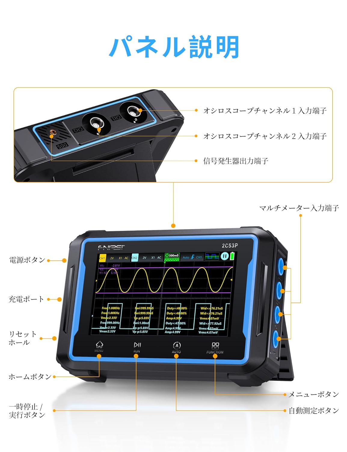
Figure 4.1: FNIRSI 2C53P with labeled components. Key components include Oscilloscope Channel 1 & 2 inputs, Signal Generator output, Multimeter input terminals, Power button, Charging port, Reset hole, Home button, Menu button, Run/Pause button, Auto button, and Function button.

Figure 4.2: Detailed view highlighting the device's ports (VΩDFC, Com, mA, 10A, CH1, CH2, DDS), reinforced glass touch panel, compact design, 90-degree adjustable integrated stand, and impact-resistant protective structure.
Key Components:
- 4.3-inch IPS Touch Screen: High-resolution (480*272) display for clear waveform visualization and intuitive control.
- Oscilloscope Input (CH1, CH2): BNC connectors for probe connection.
- Signal Generator Output (DDS): Output for various waveforms.
- Multimeter Input Terminals (VΩDFC, Com, mA, 10A): For connecting test leads for multimeter functions.
- Power Button: Turns the device on/off.
- Type-C Charging Port: For charging the internal 4000mAh battery.
- Control Buttons: Home, Menu, Run/Pause, Auto, Function buttons for navigation and mode selection.
5. Setup
5.1 Initial Charging
Before first use, fully charge the device using the provided Type-C charging cable and a compatible 5V/1A power adapter. The charging port is located on the side of the device.

Figure 5.1: The FNIRSI 2C53P features a built-in 4000mAh rechargeable battery and a convenient Type-C charging port.
5.2 Connecting Probes and Test Leads
- For Oscilloscope: Connect the P6100 high voltage probes to the BNC connectors labeled CH1 and CH2. Ensure a secure connection.
- For Multimeter: Connect the test leads to the appropriate multimeter input terminals (e.g., COM and VΩDFC for voltage/resistance, COM and mA/10A for current).
- For Signal Generator: Connect the alligator clip or other appropriate connector to the DDS output port.
5.3 Power On/Off
Press and hold the Power button located on the side of the device to turn it on or off.
6. Operating Instructions
The FNIRSI 2C53P offers three primary functions: Oscilloscope, Multimeter, and Signal Generator. Use the touch screen and physical buttons to navigate between modes and adjust settings.

Figure 6.1: The FNIRSI 2C53P integrates an oscilloscope, multimeter, and signal generator into one device.
6.1 Oscilloscope Mode
The oscilloscope function allows for real-time visualization and analysis of electrical signals.

Figure 6.2: Oscilloscope mode showing a waveform with the 20MHz bandwidth limit enabled, optimizing for precise detection of small signals by filtering high-frequency noise.
- Channel Selection: The device supports 2 channels. Select the desired channel(s) for measurement.
- Bandwidth Limit: Activate the 20MHz bandwidth limit function to reduce high-frequency noise, especially useful for analyzing power ripples or small signals.
- Trigger Functions: Use Auto, Normal, or Single trigger modes to stabilize waveforms.
- Automatic Measurement: The device can automatically display various waveform parameters.
- Waveform Analysis: Features include mathematical operations, FFT (Fast Fourier Transform) spectral analysis, Lissajous figures, persistence display, and cursor measurement.
- Waveform Storage: Save waveform screenshots and export them via USB connection to a computer.

Figure 6.3: Advanced waveform analysis capabilities including persistence display, X-Y mode, FFT spectrum, and cursor measurement.
6.2 Multimeter Mode
The multimeter function provides precise measurements of various electrical parameters.

Figure 6.4: Multimeter mode showing 19999 counts True RMS measurement with a real-time curve display for visual confirmation of changes.
- Measurement Range: Measures DC/AC Voltage (up to 1000V DC, 760V AC), DC/AC Current (up to 10A), Resistance, Capacitance, Diode, Continuity, and Temperature.
- True RMS: Provides accurate readings for non-sinusoidal waveforms.
- Real-time Curve Display: Visualize measurement trends over time, recording up to 5 measurement values.
- Safety: Equipped with dual ceramic fuses for high voltage and overcurrent protection.

Figure 6.5: The FNIRSI 2C53P is a versatile measurement tool, capable of measuring DC voltage, AC voltage, resistance, capacitance, large current, small current, temperature, diode, and continuity.
6.3 Signal Generator Mode
The signal generator can output various waveforms with adjustable parameters.

Figure 6.6: The signal generator offers 12 types of waveforms including Sine, Square, Sawtooth, Half-wave, Full-wave, Step, Inverse Step, DC signal, Exponential Rise, Exponential Fall, Multi-audio, and Sink Pulse.
- Waveform Types: Select from 12 different waveforms including Sine, Square, Sawtooth, Half-wave, Full-wave, Step, Inverse Step, DC signal, Exponential Rise, Exponential Fall, Multi-audio, and Sink Pulse.
- Frequency Adjustment: Sine wave frequency up to 10MHz; other waveforms up to 5MHz.
- Amplitude Control: Adjust output amplitude from 0.1V to 3V.
- Duty Cycle: Adjustable from 0% to 100% for square waves and other relevant waveforms.
6.4 PC Connection (USB Share)
The device supports USB connection to a computer for viewing and exporting saved waveform images.

Figure 6.7: Connect the device to a PC via USB to save, check, and delete waveform images.
7. Maintenance
Proper maintenance ensures the longevity and accuracy of your FNIRSI 2C53P.
- Cleaning: Use a soft, dry cloth to clean the device. Do not use abrasive cleaners or solvents.
- Battery Care: For optimal battery life, avoid fully discharging the device frequently. If storing for extended periods, charge the battery to approximately 50-70%.
- Storage: Store the device in a cool, dry place, away from direct sunlight and extreme temperatures.
- Probe and Lead Inspection: Regularly inspect probes and test leads for any signs of damage (e.g., frayed wires, cracked insulation). Replace damaged accessories immediately.
8. Troubleshooting
If you encounter issues with your FNIRSI 2C53P, refer to the following common troubleshooting steps.
- Device does not power on: Ensure the battery is charged. Connect the Type-C charging cable and try again.
- No waveform displayed in Oscilloscope mode: Check probe connections. Ensure the trigger settings are appropriate for the signal being measured. Adjust vertical and horizontal scales.
- Inaccurate multimeter readings: Verify test lead connections to the correct terminals. Ensure the correct measurement function is selected. Check for damaged test leads.
- Signal generator output issues: Confirm the DDS output is connected correctly. Check frequency, amplitude, and duty cycle settings.
- Firmware Update: If experiencing unexpected behavior, check the official FNIRSI website or product page for available firmware updates. Firmware updates can resolve bugs and improve functionality. Refer to the instruction manual for the update procedure.
- Screen Unresponsive: If the touch screen is unresponsive, try restarting the device. If the issue persists, a factory reset might be necessary (refer to the device settings menu).
For persistent issues, please contact customer support.
9. Specifications
Below are the detailed technical specifications for the FNIRSI 2C53P.

Figure 9.1: General and Oscilloscope Parameters.

Figure 9.2: Signal Generator and Multimeter Parameters.
| Feature | Specification |
|---|---|
| Display | 4.3-inch IPS Color Display, 480*272 Resolution |
| Power Supply | Type-C (5V/1A) |
| Battery | 4000mAh Lithium Polymer Battery |
| Dimensions | 14.5 x 9.8 x 3.5 cm |
| Weight | 360 g |
| Measurement Accuracy | +/-5% |
| Feature | Specification |
|---|---|
| Channel Count | 2 |
| Analog Bandwidth | 50MHz |
| Real-time Sample Rate | 250MSa/s |
| Memory Depth | Max 64KB |
| Vertical Sensitivity | 10mV/div ~ 10V/div |
| Time Base Range | 10ns/div ~ 10s/div |
| Input Impedance | 1MΩ |
| Coupling | AC/DC |
| Max Input Voltage | ±400V |
| Bandwidth Limit | 20MHz supported |
| Trigger Modes | Auto, Normal, Single |
| Storage Capacity | 12M |
| Measurement | Range | Accuracy |
|---|---|---|
| DC Voltage | 1.9999V/19.999V/199.99V/1000.0V | ±(0.5%+3) |
| AC Voltage | 1.9999V/19.999V/199.99V/750.0V | ±(1%+3) |
| DC Current | 19.999mA/199.99mA/1.9999A/9.999A | ±(1.2%+3) |
| AC Current | 19.999mA/199.99mA/1.9999A/9.999A | ±(1.5%+3) |
| Resistance | 19.999MΩ/1.9999MΩ/199.99KΩ/19.999KΩ/1.9999KΩ/199.99Ω | ±(0.5%+3) |
| Capacitance | 999.9uF/99.99uF/9.999uF/999.9nF/99.99nF/9.999nF/999.9mF/99.99mF | ±(0.5%+3) |
| Temperature | -55 ~ 1300°C / -67 ~ 2372°F | ±(2.0%+5) |
| Diode | Support | ±(5.0%+20) |
| Continuity | Support | ±(2.5%+5) |
| Feature | Specification |
|---|---|
| Frequency Range | Sine wave: 0 ~ 10MHz; Other waveforms: 0 ~ 5MHz |
| Amplitude | 0.1V ~ 3V |
| Duty Cycle | 0 ~ 100% |
10. Warranty and Support
FNIRSI products are designed for reliability and performance. For warranty information, please refer to the documentation included with your purchase or visit the official FNIRSI website.
Customer Support:
If you have any questions, require technical assistance, or need to report an issue, please contact FNIRSI customer support through the following methods:
- Amazon Messaging: For purchases made on Amazon, you can contact the seller directly through your Amazon order history.
- Email Support: Reach out to FNIRSI after-sales service center at support@fnirsi.com. When sending an email, please include your order number and a detailed description of your inquiry.
- Product Page: Additional resources, including downloadable manuals and firmware updates, may be available on the product's Amazon page or the official FNIRSI website.


