
Introduction
This manual provides essential information for the installation, operation, and maintenance of the Bloepum F722 Stack F7 Flight Controller and BLS-60A 4in1 ESC. Please read this manual thoroughly before use to ensure proper functionality and safety.
The F722 Stack is designed for FPV drones, offering a high-performance flight controller and a robust 4-in-1 Electronic Speed Controller (ESC) for reliable flight control.
Product Overview

Image 1: Assembled F722 Flight Controller and BLS-60A 4in1 ESC stack.

Image 2: Individual components of the F722 Stack Kit, including the flight controller, 4in1 ESC, connection wires, and capacitor.
Key Features:
- F722 Flight Controller: STM32F722RET6 MCU, -42688 IMU, AT7456E OSD, SPL06-001 Barometer, 16MB Blackbox, 3-8S Lipo input, Dual BEC (5V/2.5A, 10V/2A).
- BLS-60A 4in1 ESC: 3-6S Lipo input, 60A continuous current, 65A burst current (10s), EF8BB21 Processor, supports DShot150-600, Multishot, Oneshot, PWM.
- High-quality capacitors for strong filtering performance.
- Robust PCB design with high overcurrent capability and good heat dissipation.
- Low consumption MOS for strong load capacity.
Specifications
| Component | Specification |
|---|---|
| Flight Controller (F722) | |
| MCU | STM32F722RET6 |
| IMU | -42688 |
| OSD | AT7456E |
| Barometer | SPL06-001 |
| Blackbox | 16MB |
| Input Voltage | 3-8S Lipo (11.4-36V) |
| 5V-BEC Output | 5V/2.5A ±0.1V |
| 10V-BEC Output | 10V/2A (USER1) |
| Receiver Support | ELRS (CRSF), TBS (CRSF), SBUS, IBUS, DSM2, DSMX |
| UARTs | UART1/2/3/4/5/6 |
| IIC | I2C1 |
| LED Strip | Yes |
| Buzzer | 5V |
| USB Port | TYPE-C |
| Current Sensor | Yes |
| Voltage Sensor | Yes |
| DFU Button | Yes |
| Firmware | Betaflight 4.3.1 JHEF7DUAL.HEX |
| Mounting Hole | 30.5x30.5x4MM |
| 4in1 ESC (BLS-60A) | |
| Aperture | 30.5 x 30.5mm (after installing the ball, the aperture is 3mm) |
| Firmware | BLHELI-S |
| Input Voltage | LIPO 3-6S |
| Continuous Current | 60A |
| Maximum Current | 65A (10 seconds) |
| Processor | EF8BB21 |
| Drive Signal Support | DShot150-300-600/Multishot/Oneshot/PMW |
| Current Sensor | Supports |
| General | |
| Material | PCB |
| Color | Black |
| Dimensions | 30.5mm x 30.5mm x 4mm (Mounting Hole) |
| Weight | 57 g (approximate total stack weight) |
Setup and Installation
Proper installation is crucial for the performance and safety of your drone. Refer to the wiring diagrams and pinouts carefully.
1. Physical Mounting
- Mount the F722 Flight Controller and BLS-60A 4in1 ESC stack onto your drone frame using the provided mounting hardware.
- Ensure the stack is securely fastened and isolated from vibrations. The mounting holes are 30.5x30.5mm.
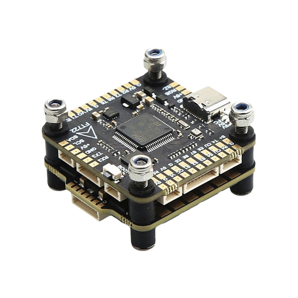
Image 3: Top view of the F722 Flight Controller, highlighting the USB-C port and connection pads.

Image 4: Angled view of the F722 Flight Controller, illustrating the layout of various connection points and pads.
2. Wiring Connections
Connect the flight controller to the 4in1 ESC using the provided ribbon cable or individual wires, ensuring correct pin alignment for power, ground, and signal lines (e.g., DShot).
- Power Input: Connect your LiPo battery (3-8S for FC, 3-6S for ESC) to the main power pads on the ESC. Ensure correct polarity.
- Motors: Connect motor wires to the corresponding pads on the 4in1 ESC.
- Receiver: Connect your receiver (ELRS, TBS, SBUS, IBUS, DSM2, DSMX) to the appropriate UART on the flight controller. Refer to the FC pinout for specific UART assignments.
- FPV Camera/VTX: Utilize the 5V or 10V BEC outputs for powering your FPV camera and video transmitter.
- Peripherals: Connect other peripherals like GPS, LED strips, or buzzers to their designated pads.

Image 5: Side view of the F722 Stack, illustrating the various connection ports and headers for peripherals.

Image 6: Another angled view of the F722 Stack, providing a clearer perspective of the connection pads and their labels.
3. Firmware Flashing and Configuration
- Connect the flight controller to your computer via the USB Type-C port.
- Open Betaflight Configurator (or similar flight control software).
- Flash the recommended firmware (Betaflight 4.3.1 JHEF7DUAL.HEX) if necessary.
- Configure your receiver, motors, ESC protocols (DShot600 recommended), OSD, and other settings according to your drone build and preferences.
- Calibrate the accelerometer and gyroscope.
Operating Instructions
Pre-Flight Checks:
- Ensure all connections are secure and free from shorts.
- Verify propeller direction and motor spin direction in Betaflight.
- Check battery voltage and ensure it is within the safe operating range.
- Confirm radio control functionality and arming switch.
First Flight:
- Perform the first flight in an open, safe area away from people and obstacles.
- Start with gentle throttle inputs and observe drone behavior.
- Land immediately if any unusual behavior is observed.
Maintenance
- Regular Inspection: Periodically check for loose connections, damaged wires, or signs of overheating on the FC and ESC.
- Cleaning: Keep the boards free from dust, dirt, and moisture. Use compressed air or a soft brush for cleaning.
- Firmware Updates: Check for new firmware releases for Betaflight and BLHeli-S to benefit from performance improvements and bug fixes.
- Heat Management: Ensure adequate airflow around the stack, especially the ESC, to prevent overheating during aggressive flight.
Troubleshooting
- Drone not arming:
- Check Betaflight configurator for arming flags (e.g.,
NO_GYRO,RX_LOSS,FAILSAFE). Ensure your radio is connected and calibrated, and the arming switch is correctly assigned. - Motors not spinning correctly:
- Verify motor direction in Betaflight. Check ESC protocol settings (DShot, Multishot). Ensure motor wires are securely connected and not shorted.
- No OSD display:
- Confirm OSD is enabled in Betaflight. Check video signal connections between camera, FC, and VTX. Ensure correct NTSC/PAL setting.
- Intermittent power issues:
- Inspect all power connections, especially the main battery lead and capacitor. Check for cold solder joints or damaged wires. Ensure battery voltage is sufficient.
Safety Information
- Always remove propellers before connecting the battery for configuration or testing.
- Never operate your drone near people, animals, or property.
- Be aware of local regulations regarding drone operation.
- Use appropriate safety gear, such as safety glasses, when working with soldering irons or power tools.
- Ensure proper ventilation when soldering.
Warranty and Support
For warranty information and technical support, please contact Bloepum customer service through the retailer where the product was purchased. Please provide your purchase details and model number (500804014) when seeking support.
For general information and community support regarding Betaflight and BLHeli-S, refer to their official documentation and forums online.