
1. Introduction
This manual provides detailed instructions for the Aoleaby XR35CX-5N7I3 Temperature Controller. This device is designed for precise temperature control in cold storage and refrigeration applications, ensuring optimal performance and energy efficiency. Please read this manual thoroughly before installation and operation to ensure correct usage and to prevent damage.
2. Safety Information
Always observe the following safety precautions:
- Disconnect power before performing any wiring or maintenance.
- Ensure all wiring complies with local electrical codes and regulations.
- Do not expose the controller to water or excessive humidity.
- Only qualified personnel should install and service this device.
- Verify the power supply voltage matches the controller's specifications (230V~, 50-60Hz).
3. Product Overview
The Aoleaby XR35CX-5N7I3 is a compact and reliable temperature controller featuring a digital display and intuitive button interface. It is suitable for various refrigeration units.
3.1 Front Panel
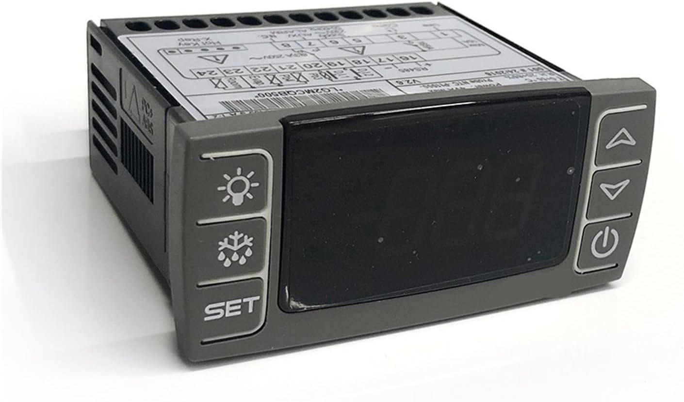
Figure 1: Front view of the Aoleaby XR35CX-5N7I3 Temperature Controller, showing the digital display and control buttons. From left to right, the buttons are for light, defrost, and set. On the right side, there are up, down, and power buttons.
The front panel includes a digital display for temperature readings and status indicators, along with several control buttons:
- SET Button: Used to enter parameter setting mode or confirm values.
- Defrost Button (Snowflake icon): Manually initiates a defrost cycle.
- Light Button (Lightbulb icon): Controls the internal light of the refrigeration unit (if connected).
- Up Arrow Button: Increases values or navigates through menus.
- Down Arrow Button: Decreases values or navigates through menus.
- Power Button: Turns the controller on/off or exits parameter setting mode.
3.2 Rear Panel and Wiring Terminals

Figure 2: Rear view of the Aoleaby XR35CX-5N7I3 Temperature Controller, displaying the wiring diagram and terminal blocks. Key labels include "Line", "Comp", "Supply", "AUX/ALARM", "N.C.", "Hot Key X-Rep", and probe connections for NTC-Pt1000.
The rear panel contains the terminal blocks for electrical connections. Refer to the wiring diagram printed on the unit for specific connections. The model number "LG2MCQB500" is also visible on the label.
4. Setup and Installation
Proper installation is crucial for the controller's performance and safety.
4.1 Mounting
The controller is designed for panel mounting. Ensure adequate space for ventilation and access to wiring terminals. Cut an opening in the panel according to the controller's dimensions (refer to specifications for exact measurements).
4.2 Wiring
Before wiring, ensure the main power supply is disconnected. Follow the wiring diagram carefully. The controller supports NTC-Pt1000 probes.
| Terminal No. | Description |
|---|---|
| 1 | Line (Power Input) |
| 3 | Compressor Output |
| 5, 6, 7, 8 | Supply 230V~, AUX/ALARM, N.C. (Refer to diagram for specific functions) |
| 16, 17 | RS485 Communication |
| 18, 19, 20 | Probe NTC-Pt1000 (D12, C11, Evap) |
| 21, 22, 23, 24 | Evap, Room (Additional probe/sensor connections) |
Ensure all connections are secure to prevent loose contacts and potential hazards.
5. Operating Instructions
This section details the basic operation and parameter settings of the controller.
5.1 Power On/Off
Press and hold the Power Button for approximately 3 seconds to turn the controller on or off.
5.2 Viewing the Setpoint
Press and release the SET Button. The display will show the setpoint value. Press SET again or wait 5 seconds to return to the normal temperature display.
5.3 Changing the Setpoint
- Press and release the SET Button. The display will show the setpoint value.
- Within 5 seconds, press and hold the SET Button for approximately 2 seconds. The setpoint value will start flashing.
- Use the Up Arrow or Down Arrow buttons to adjust the setpoint to the desired temperature.
- Press the SET Button to confirm the new value and exit the setting mode.
5.4 Manual Defrost
Press and hold the Defrost Button (Snowflake icon) for approximately 3 seconds to initiate a manual defrost cycle. The defrost indicator will illuminate.
5.5 Accessing Parameter Menu
To access advanced parameters, press and hold the SET Button and Down Arrow Button simultaneously for approximately 3 seconds. Use the Up Arrow and Down Arrow buttons to navigate through parameters and the SET Button to view/edit values. Refer to the full technical manual for a complete list of parameters and their functions.
6. Maintenance
Regular maintenance ensures the longevity and optimal performance of your temperature controller.
- Cleaning: Gently wipe the front panel with a soft, damp cloth. Do not use abrasive cleaners or solvents. Ensure no liquid enters the controller.
- Inspections: Periodically check wiring connections for tightness and signs of wear or corrosion.
- Probe Check: Ensure temperature probes are clean and securely positioned for accurate readings.
7. Troubleshooting
This section addresses common issues you might encounter.
| Problem | Possible Cause | Solution |
|---|---|---|
| Controller does not power on. | No power supply; incorrect wiring; blown fuse. | Check power connections; verify wiring against diagram; check and replace fuse if necessary. |
| Display shows "P1" or "P2" error. | Probe error (P1 for room probe, P2 for evaporator probe). | Check probe connections; replace faulty probe if needed. |
| Temperature reading is inaccurate. | Faulty probe; probe not correctly positioned; calibration issue. | Check probe placement; verify probe functionality; recalibrate if necessary (refer to advanced parameter settings). |
| Compressor not starting/stopping as expected. | Incorrect setpoint; parameter settings incorrect; faulty compressor relay. | Verify setpoint and differential settings; check compressor wiring; consult a technician if relay is suspected. |
For issues not listed here or if solutions do not resolve the problem, contact technical support.
8. Specifications
| Feature | Detail |
|---|---|
| Model | XR35CX-5N7I3 |
| Brand | Aoleaby |
| Power Supply | 230V~, 50-60Hz |
| Probe Type | NTC-Pt1000 |
| Max Current (Compressor) | 16A |
| Operating Temperature | 0 to +55 °C |
| Relative Humidity | 20-85% (non-condensing) |
| Package Dimensions | 1.18 x 0.79 x 0.39 inches |
| Item Weight | 1.32 pounds |
9. Warranty and Support
For warranty information or technical support, please refer to the product packaging or contact your retailer. Keep your purchase receipt for warranty claims.