1. Overview
The SC26-2DE Safety Controller is a non-expandable, high-performance safety device designed for industrial applications. It features 26 inputs, including 8 convertible inputs, and 2 pairs of PNP safety outputs, each rated at 0.5 A. The controller is equipped with a display for status indication and configuration, and offers Ethernet and USB interfaces for communication and programming. Its robust design and removable screw terminals facilitate easy installation and maintenance.
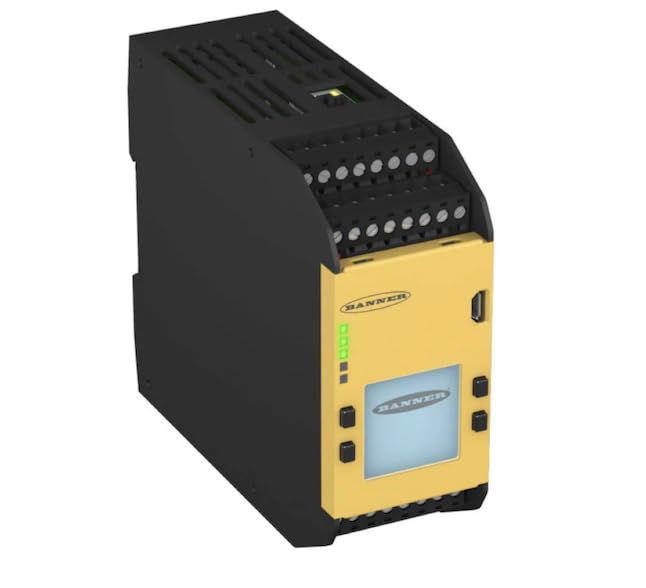
Figure 1: SC26-2DE Safety Controller. This image shows the compact, rectangular safety controller with a yellow front panel and black housing. The front panel features a display screen, several indicator LEDs, and removable screw terminals for electrical connections. The top and bottom sections also have screw terminals for inputs and outputs.
2. Setup and Installation
Proper installation is crucial for the safe and reliable operation of the SC26-2DE Safety Controller. Follow these guidelines carefully:
- Mounting: Mount the controller on a DIN rail in a suitable enclosure, ensuring adequate ventilation and protection from environmental factors such as dust, moisture, and extreme temperatures.
- Power Connection: Connect the power supply to the designated terminals. Ensure the power source meets the voltage and current requirements specified in the technical specifications. Observe correct polarity.
- Input Wiring: Wire safety devices (e.g., light curtains, E-stop buttons, interlock switches) to the 26 input terminals. Pay close attention to the wiring diagrams provided in the detailed product documentation for specific sensor types. Eight of these inputs are convertible and can be configured as standard inputs or other functions.
- Output Wiring: Connect the safety outputs (PNP, 0.5 A each pair) to the controlled devices, such as contactors or relays. Verify that the load current does not exceed the specified output rating.
- Communication Interfaces:
- Ethernet: Connect an Ethernet cable for network communication, remote monitoring, and configuration.
- USB: Use the Micro USB port for direct connection to a computer for initial setup, programming, and firmware updates.
- Terminal Connections: Utilize the removable screw terminals for secure and reliable electrical connections. Ensure all wires are properly seated and tightened to prevent loose connections.
- Configuration: Use the appropriate software tool (typically provided by the manufacturer) to configure the safety logic, input/output functions, and communication settings. Refer to the software manual for detailed configuration instructions.
3. Operating Instructions
Once installed and configured, the SC26-2DE operates autonomously based on the programmed safety logic. Here are key operational aspects:
- Power-Up: Upon applying power, the controller performs a self-diagnostic check. The display and indicator LEDs will show the system status.
- Status Indicators: Monitor the LEDs on the front panel for operational status. Green LEDs typically indicate normal operation, while red or flashing LEDs may indicate a fault or warning. Consult the fault codes in the troubleshooting section.
- Display Interface: The integrated display provides real-time status, fault messages, and allows for basic parameter viewing or navigation through menus, depending on the configuration.
- Safety Function Activation: The controller continuously monitors the connected safety inputs. If a safety input is triggered (e.g., E-stop pressed, light curtain interrupted), the controller will execute the programmed safety reaction, typically de-energizing the safety outputs to bring the machinery to a safe state.
- Resetting Safety Functions: After a safety function has been activated, the system typically requires a manual or automatic reset, as configured, before normal operation can resume. Ensure the cause of the safety activation is resolved before resetting.
- Communication: The Ethernet interface allows for integration into industrial networks for remote diagnostics, data logging, and supervisory control. The USB port is primarily for local programming and diagnostics.
4. Maintenance
Regular maintenance ensures the longevity and continued safe operation of your SC26-2DE Safety Controller:
- Visual Inspection: Periodically inspect the controller for any signs of physical damage, loose connections, or excessive dust accumulation.
- Cleaning: Clean the exterior of the controller with a soft, dry cloth. Do not use abrasive cleaners or solvents. Ensure the display remains clear and readable.
- Terminal Tightness: Check the tightness of all screw terminals annually or as part of a routine maintenance schedule to ensure secure electrical connections.
- Firmware Updates: Check the manufacturer's website periodically for firmware updates. Applying updates can improve performance, add features, or address known issues. Follow the provided instructions for firmware update procedures.
- Functional Testing: Regularly test the safety functions connected to the controller as per your facility's safety protocols and relevant standards (e.g., ISO 13849, IEC 62061). This includes testing E-stops, light curtains, and interlocks.
5. Troubleshooting
This section provides guidance for common issues encountered with the SC26-2DE Safety Controller.
| Problem | Possible Cause | Solution |
|---|---|---|
| Controller does not power on. | No power supply; incorrect wiring; faulty power supply. | Verify power connections and voltage. Check power supply unit. Ensure correct polarity. |
| Safety outputs remain de-energized. | Safety input triggered; fault condition; system not reset. | Check all safety inputs for active triggers. Resolve any fault conditions indicated by LEDs/display. Perform a system reset. |
| Display shows an error code. | Internal fault; configuration error; external wiring issue. | Note the error code and consult the detailed fault code list in the full product manual. Check wiring and configuration. |
| Cannot connect via Ethernet/USB. | Incorrect cable; driver issue; network settings; software not running. | Ensure correct cable type. Install necessary drivers. Verify network settings (IP address). Ensure configuration software is running. |
For more complex issues or persistent problems, refer to the comprehensive troubleshooting guide available on the manufacturer's website or contact technical support.
6. Technical Specifications
| Feature | Specification |
|---|---|
| Model | SC26-2DE |
| Product Type | Safety Controller |
| Expandability | Non-expandable |
| Total Inputs | 26 |
| Convertible Inputs | 8 |
| Safety Outputs | 2 Pairs of PNP Safety Outputs (0.5 A Each) |
| Interface Types | Ethernet, Micro USB |
| Display | Integrated Display |
| Terminals | Removable Screw Terminals |
| Item Weight | 16.99 Pounds (approx. 7.7 kg) |
| Manufacturer | BANNER ENGINEERING |
7. Support Information
For further assistance, technical support, or to access the latest documentation and software, please visit the official BANNER ENGINEERING website or contact their customer service department. Always refer to the complete product manual for detailed safety information, wiring diagrams, and programming instructions.
Note: Specifications are subject to change without notice. Always refer to the latest product documentation for the most accurate information.


