
Introduction
This instruction manual provides detailed guidance for assembling and operating your BANRIA DIY Soldering Kit Humidifier. This kit is designed to enhance soldering skills and provide insight into the internal mechanisms and circuit design of a functional humidifier. It is suitable for educational purposes and personal projects.
The completed device features an OLED display for real-time temperature and humidity readings, along with timer and memory functions.
Package Contents
Before beginning assembly, please verify that all components listed below are present in your kit.

Figure 1: All components included in the BANRIA DIY Soldering Kit Humidifier package. This includes the main PCB, OLED display, various resistors, capacitors, buttons, sensors, a nebulizer, USB cable, and acrylic casing parts.
- Main Printed Circuit Board (PCB)
- OLED Display Module
- Temperature and Humidity Sensor
- Ultrasonic Nebulizer Plate
- Control Buttons (4x)
- Resistors, Capacitors, Diodes, and Integrated Circuits
- USB Power Cable
- Acrylic Casing Components
- Cotton Swab for Humidifier
- Mounting Hardware (screws, standoffs)
Setup and Assembly
This kit requires soldering. Basic soldering tools (soldering iron, solder, desoldering braid/pump, safety glasses) are necessary and not included. Follow these steps carefully for successful assembly.
- Prepare the PCB: Identify all components and their corresponding positions on the PCB. Refer to the included wiring diagrams.
- Solder Small Components First: Begin by soldering smaller components such as resistors, diodes, and smaller capacitors. Ensure correct polarity for diodes and electrolytic capacitors.
- Install Integrated Circuits (ICs): If using IC sockets, solder the sockets first, then carefully insert the ICs, observing pin 1 orientation. If soldering ICs directly, ensure correct orientation.
- Solder Buttons and Connectors: Attach the four control buttons and any other connectors (e.g., USB port, sensor headers).
- Mount OLED Display: Solder the OLED display module to its designated pins on the PCB.
- Connect Temperature and Humidity Sensor: Solder the sensor to its designated pins.
- Install Nebulizer Plate: Connect the ultrasonic nebulizer plate to the PCB. Ensure a secure connection.
- Assemble Casing: Once all electronic components are soldered, assemble the acrylic casing around the PCB using the provided standoffs and screws.
- Insert Cotton Swab: Insert the cotton swab into the nebulizer housing. Ensure it is fully saturated with water before first use.

Figure 2: The fully assembled humidifier kit in operation, demonstrating mist output and the OLED display.
Operating Instructions
The humidifier is powered by a 5V USB power supply. It features an OLED display and four control buttons for operation.

Figure 3: Detailed view of the humidifier's components and controls, including the OLED screen, power switch, nebulizer plate, and control buttons (KEY0, KEY1, KEY2, KEY3).
Powering On/Off
- Connect the USB cable to a 5V USB power source.
- Press the Power Switch (labeled SW1 in Figure 3) to turn the device on or off.
OLED Display Information
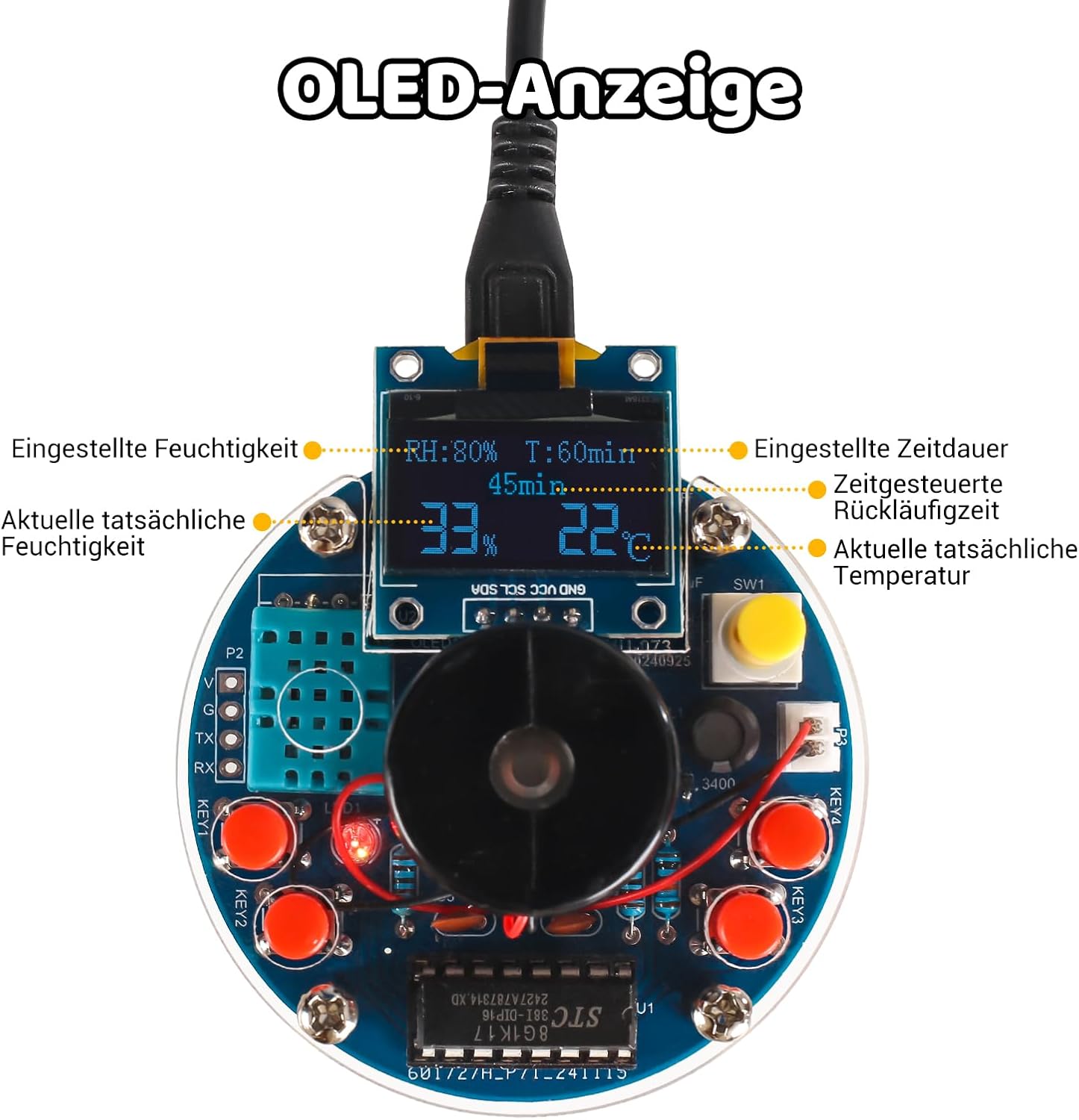
Figure 4: The OLED display showing real-time data and settings. This includes set humidity (RH%), actual humidity (%), set timer (T:XXmin), timed countdown (XXmin), and actual temperature (°C).
The OLED display provides the following information:
- RH: Set Humidity Percentage
- T: Set Timer in Minutes
- Actual Humidity: Current humidity percentage in the environment
- Actual Temperature: Current temperature in Celsius
- Countdown: Remaining time for the set timer
Button Functions
The four buttons (KEY0, KEY1, KEY2, KEY3) are used to navigate menus and adjust settings. Specific functions may vary based on the current mode.
- KEY0 (Right-most): Typically used for selection or confirmation.
- KEY1 (Bottom-right): Often used to increase values or move right in menus.
- KEY2 (Bottom-left): Often used to decrease values or move left in menus.
- KEY3 (Left-most): Typically used to enter/exit setting mode or change language.
To enter the settings menu, press the bottom-left button (KEY2). Navigate options using KEY1 and KEY2, and confirm with KEY0. To turn off the LED display, enter the menu using KEY2, then press the top-left button (KEY3) at the fourth option.
Maintenance
- Cotton Swab Replacement: The cotton swab should be replaced periodically, especially if mist output decreases or if it appears discolored. Ensure the new swab is fully saturated with water before use.
- Cleaning: Gently wipe the exterior of the device with a dry or slightly damp cloth. Do not immerse the device in water.
- Nebulizer Plate: If mist output is low, the nebulizer plate may need cleaning. Use a soft brush or cotton swab with a small amount of vinegar to gently clean the surface, then rinse with clean water.
- Storage: When not in use for extended periods, disconnect the power, ensure the cotton swab is dry, and store the device in a cool, dry place.
Troubleshooting
| Problem | Possible Cause | Solution |
|---|---|---|
| Device does not power on. | No power from USB source; faulty USB cable; incorrect soldering. | Check USB power source and cable. Verify all power connections and soldering points on the PCB. |
| No mist output. | Cotton swab not saturated; nebulizer plate dirty or faulty; insufficient water. | Ensure cotton swab is fully wet. Clean the nebulizer plate. Ensure the device is placed over a water reservoir. |
| OLED display is blank or shows incorrect readings. | OLED module not connected correctly; sensor faulty or incorrectly soldered. | Check connections to the OLED module and temperature/humidity sensor. Verify soldering. |
| Buttons are unresponsive. | Buttons incorrectly soldered; faulty buttons. | Inspect button soldering points. Ensure buttons are correctly oriented. |
If you encounter persistent issues, please review the assembly steps and soldering connections carefully. For further assistance, contact BANRIA customer support.
Specifications
| Feature | Detail |
|---|---|
| Model Number | EM21712-DE |
| Brand | BANRIA |
| Power Supply | 5V USB |
| Display Type | OLED |
| Functions | Temperature Display, Humidity Display, Timer, Memory Function |
| Material | PCB, Acrylic |
| Product Dimensions (L x W x H) | 12 x 8 x 3 cm (approx.) |
| Item Weight | 76 Grams |
| Assembly Required | Yes (Soldering) |
| Recommended Age | Adult (or 12+ with supervision due to soldering) |

Figure 5: Approximate dimensions of the assembled humidifier: 60mm width, 23.6mm height (excluding cotton swab), and 100mm cotton swab length.
Warranty and Support
BANRIA provides comprehensive support for its products. While this is a DIY kit, assistance is available for assembly and operational issues.
- Warranty: Please refer to the retailer's return policy or contact BANRIA directly for specific warranty information.
- Technical Support: If you encounter any problems during soldering or operation, or have questions regarding the kit, please contact BANRIA customer support. Experienced technicians are available to assist you.
- Online Resources: Additional resources, including detailed wiring diagrams and community forums, may be available on the BANRIA official website or through the retailer.
