
1. Introduction
The AYWHP PN532 NFC NXP RFID Module V3 Kit is a versatile Near Field Communication (NFC) and Radio-Frequency Identification (RFID) module designed for various applications. It supports wireless communication with Android phones and is compatible with development platforms like Arduino and Raspberry Pi. This module offers multiple operating modes, including I2C, SPI, and HSU (High-Speed UART), ensuring flexible integration into your projects. Its high-speed data transmission capabilities provide stable and rapid communication for tasks such as reading and writing RFID tags, peer-to-peer data exchange, and implementing smart access control systems.

Image: The PN532 module is suitable for various applications such as smart homes, access control systems, and mobile payments in company, shopping mall, school, and residential environments.
2. Package Contents
Please verify that all the following items are included in your package:
- 3 x PN532 NFC RFID Modules
- 3 x 4-pin Cables
- 3 x Mifare One S50 White Cards
- 3 x Mifare One S50 Access Cards (Key Fobs)
- 3 x 12P Curved Male Pin Headers

Image: Overview of the PN532 NFC RFID Module V3 Kit components, including the module, white card (5.4cm x 8.5cm), key fob (3.1cm x 3.4cm), and a 20.3cm cable. The module itself measures 4cm x 4.2cm.
3. Setup
3.1 Interface Selection
The PN532 module supports three communication interfaces: I2C, SPI, and HSU (High-Speed UART). You can easily switch between these modes using the onboard switches. Refer to the module's silkscreen for switch positions corresponding to each mode.
- I2C Mode: Typically used for simpler connections with fewer pins.
- SPI Mode: Offers higher speed communication, often preferred for performance-critical applications.
- HSU (UART) Mode: A serial communication interface, useful for direct connection to microcontrollers with UART peripherals.

Image: Detailed view of the PN532 module highlighting the SDA, SCL, PWR pins, and the switches for selecting HSU, I2C, or SPI communication modes. Ensure correct switch settings for your chosen interface.
3.2 Voltage Levels
The module includes an integrated level converter. It operates with standard 5V TTL for I2C and UART (HSU) interfaces, and 3.3V TTL for the SPI interface. Ensure your microcontroller or development board's logic levels match the module's requirements for the selected interface.
3.3 Connecting to a Development Board (e.g., Arduino)
Connect the PN532 module to your development board (such as Arduino or Raspberry Pi) using the provided 4-pin cables and pin headers. The specific pin connections will depend on the chosen communication interface (I2C, SPI, or HSU) and your development board's pinout. Consult your development board's documentation for appropriate connections.
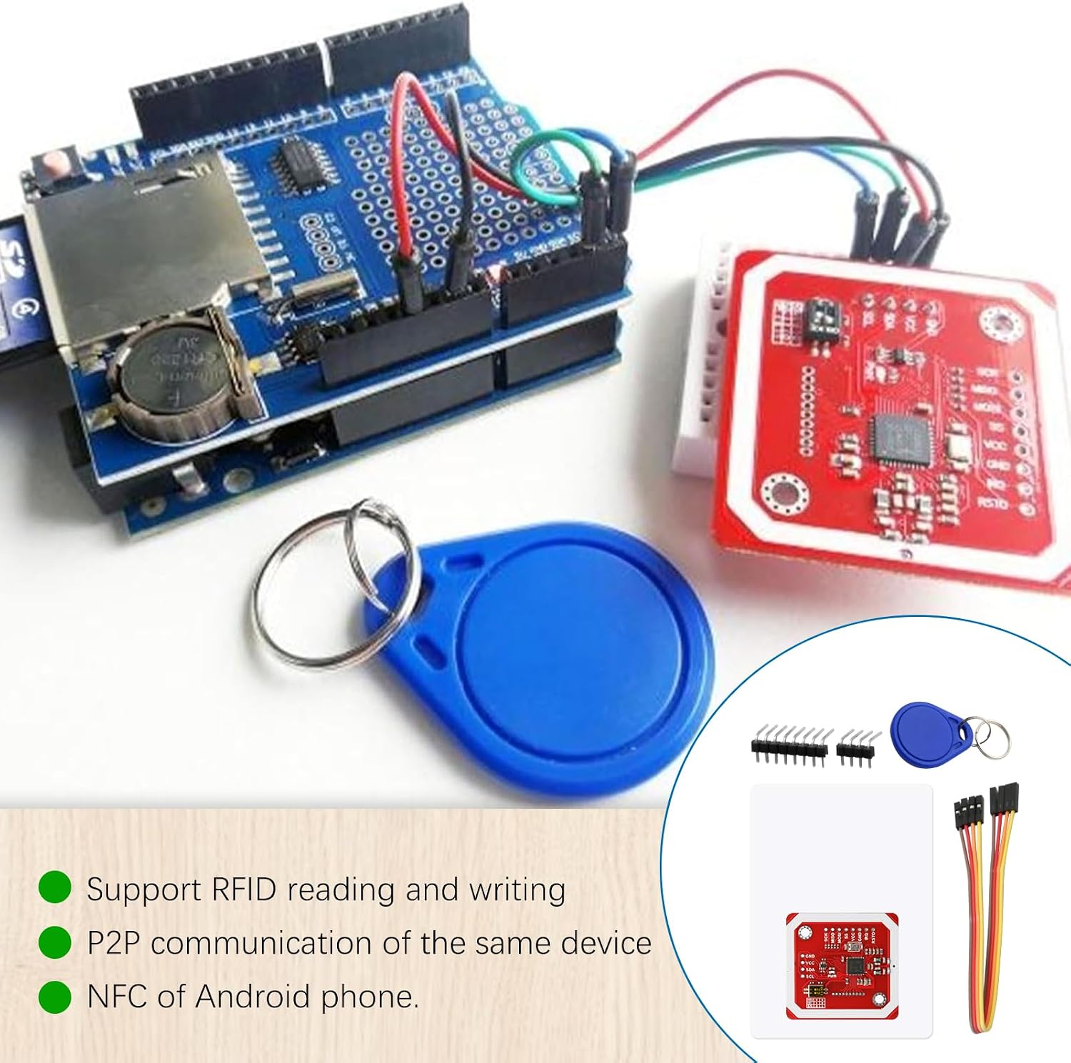
Image: The PN532 module connected to an Arduino development board, demonstrating a typical setup for RFID/NFC projects. The kit components, including the module, key fob, and white card, are shown.
4. Operating Instructions
4.1 RFID Read and Write Operations
The PN532 module functions as an RFID reader and writer. It supports a variety of RFID card types, allowing you to read data from and write data to compatible tags. This functionality is essential for applications like access control, inventory management, and data logging.
- Supported RFID Cards:
- Mifare 1k, 4k, Ultralight, and DesFire cards
- ISO/IEC 14443-4 cards such as CD97BX, CD light, Desfire, P5CN072 (SMX)
- Innovision Jewel cards, such as the IRT5001 card
- FeliCa cards such as RCS_860 and RCS_854
4.2 Peer-to-Peer (P2P) Communication
The module supports P2P communication, enabling direct data exchange between two PN532 modules or between a PN532 module and another NFC-enabled device. This is useful for short-range, secure data transfers without a central server.
4.3 NFC with Android Phones
The PN532 module is compatible with NFC-enabled Android phones, allowing for interaction with mobile applications. This feature can be utilized for various smart applications, including mobile payments, data sharing, and interactive experiences.

Image: The PN532 module supports various applications including interaction with Android devices, NFC payment systems, and general RFID card usage.
4.4 Reading Distance
The typical reading distance for the PN532 module ranges from 5 cm to 7 cm, depending on the tag type, antenna design, and environmental factors.

Image: Visual representation of the PN532 module's reading range, demonstrating its ability to detect NFC/RFID tags within 5cm to 7cm.
5. Specifications
| Feature | Detail |
|---|---|
| Model Name | PN532 NFC NXP RFID Module V3 |
| Manufacturer | AYWHP |
| Communication Interfaces | I2C, SPI, HSU (High-Speed UART) |
| Supported RFID Cards | Mifare 1k, 4k, Ultralight, DesFire; ISO/IEC 14443-4 (CD97BX, CD light, Desfire, P5CN072); Innovision Jewel (IRT5001); FeliCa (RCS_860, RCS_854) |
| Reading Distance | 5 cm ~ 7 cm |
| Integrated Level Converter | 5V TTL for I2C/UART, 3.3V TTL for SPI |
| Compatible Devices | Android phones, Arduino, Raspberry Pi |
| Package Dimensions | 18.3 x 12.5 x 2.7 cm |
| Package Weight | 60 g |
| Country of Origin | China |
6. Troubleshooting
If you encounter issues with your PN532 module, consider the following common troubleshooting steps:
- No Power: Ensure the module is correctly powered and that the power supply meets the required voltage and current.
- Communication Failure:
- Verify that the interface selection switches (I2C, SPI, HSU) are set correctly for your chosen communication protocol.
- Check all wiring connections between the module and your development board for looseness or incorrect pin assignments.
- Confirm that the logic levels (5V or 3.3V TTL) are compatible with your development board.
- Ensure your code or library is correctly configured for the selected interface.
- RFID/NFC Read Errors:
- Ensure the RFID/NFC tag is within the optimal reading distance (5-7 cm) of the module's antenna.
- Verify that the tag type is supported by the PN532 module.
- Check for any metallic objects or strong electromagnetic fields near the module that might interfere with communication.
- Module Not Detected: If your development board cannot detect the module, double-check power, ground, and communication lines. Try a different communication interface if available.
7. Safety Information
Please observe the following safety precautions when handling and operating the PN532 module:
- Static Electricity: Electronic components are sensitive to electrostatic discharge (ESD). Handle the module with care, preferably in an ESD-safe environment.
- Power Supply: Use a stable and appropriate power supply. Exceeding the recommended voltage can damage the module.
- Wiring: Ensure all connections are correct before applying power to prevent short circuits or damage.
- Environment: Avoid exposing the module to extreme temperatures, humidity, dust, or corrosive substances.
- Modifications: Do not attempt to modify the module unless you are an experienced electronics professional, as this may void any implied warranty and cause damage.
8. Warranty and Support
Warranty information for this product is not explicitly provided in the product details. For specific warranty terms or technical support, please contact the manufacturer, AYWHP, directly through their official channels or the retailer from whom the product was purchased.