
1. Introduction
This manual provides essential instructions for the safe and effective use of your Nilight 6 Gauge 12 FT Jumper Cables. Please read all instructions carefully before use to ensure proper operation and to prevent personal injury or damage to vehicles.

Image 1.1: Nilight 6 Gauge 12 FT Jumper Cables, including the carrying bag and a pair of gloves.
2. Package Contents
Verify that all items are present in the package:
- One (1) set of Nilight 6 Gauge 12 FT Jumper Cables (Red and Black)
- One (1) Storage Bag
- One (1) Pair of Gloves

Image 2.1: Visual representation of the included items: jumper cables, storage bag, and gloves.
3. Safety Precautions
- Always wear eye protection and gloves when handling car batteries and jumper cables.
- Ensure both vehicles are turned off and in park/neutral with the parking brake engaged.
- Do not allow the red and black clamps to touch each other once connected to a battery.
- Keep cables away from moving engine parts (fans, belts).
- Do not jump-start a frozen battery.
- If the battery is cracked or leaking, do not attempt to jump-start.
- Follow the connection sequence precisely to avoid sparks and potential hazards.
4. Operating Instructions: Jump-Starting a Vehicle
Follow these steps carefully to jump-start a dead battery using another vehicle:
- Position Vehicles: Park the assisting vehicle close enough to the disabled vehicle so the jumper cables can reach both batteries, but ensure the vehicles are not touching. Turn off both vehicles.
- Identify Terminals: Locate the positive (+) and negative (-) terminals on both batteries. The positive terminal is usually larger and marked with a plus sign (+). The negative terminal is marked with a minus sign (-).
- Connect Red Cable (Positive):
- Connect one end of the red (positive) jumper cable clamp to the positive (+) terminal of the dead battery.
- Connect the other end of the red (positive) jumper cable clamp to the positive (+) terminal of the assisting vehicle's battery.
- Connect Black Cable (Negative):
- Connect one end of the black (negative) jumper cable clamp to the negative (-) terminal of the assisting vehicle's battery.
- Connect the other end of the black (negative) jumper cable clamp to a clean, unpainted metal surface on the engine block or chassis of the disabled vehicle, away from the battery and fuel lines. This provides a ground connection and helps prevent sparks near the battery.
- Start Assisting Vehicle: Start the engine of the assisting vehicle and let it run for 5-10 minutes to charge the dead battery.
- Attempt to Start Disabled Vehicle: After the charging period, attempt to start the disabled vehicle. If it doesn't start immediately, wait a few more minutes and try again. Do not crank the engine for more than 5 seconds at a time.
- Disconnect Cables (Reverse Order): Once the disabled vehicle starts, disconnect the cables in the reverse order of connection:
- Disconnect the black (negative) clamp from the engine block/chassis of the disabled vehicle.
- Disconnect the black (negative) clamp from the negative (-) terminal of the assisting vehicle's battery.
- Disconnect the red (positive) clamp from the positive (+) terminal of the assisting vehicle's battery.
- Disconnect the red (positive) clamp from the positive (+) terminal of the now-started vehicle's battery.
- Keep Engine Running: Allow the newly started vehicle to run for at least 20-30 minutes to allow its battery to recharge.

Image 4.1: Step-by-step diagram for connecting jumper cables to jump-start a vehicle.

Image 4.2: Examples of jumper cables connected to vehicle batteries and engine components during a jump-start.
5. Maintenance and Storage
- After each use, inspect the cables and clamps for any signs of damage, fraying, or corrosion.
- Clean any dirt or debris from the clamps and cables with a dry cloth.
- Store the jumper cables in the provided carrying bag in a dry, cool place, away from direct sunlight and extreme temperatures.
- Ensure the clamps do not touch each other during storage.
6. Troubleshooting
- Vehicle does not start after jump-start attempt:
- Check all cable connections to ensure they are secure and making good contact.
- Ensure the assisting vehicle's engine is running.
- Allow more time for the dead battery to charge (5-10 additional minutes).
- The battery may be severely discharged or faulty and require professional service or replacement.
- There might be another issue with the disabled vehicle (e.g., starter motor, fuel system).
- Cables get hot during use:
- This can indicate excessive current draw or poor connections. Ensure clamps are securely attached.
- If cables become excessively hot, disconnect them immediately and allow them to cool.
- Sparks occur during connection:
- Some minor sparking is normal when making the final negative connection to the engine block/chassis.
- Excessive sparking may indicate incorrect connection order or a short circuit. Review safety precautions and connection steps.
7. Specifications
| Feature | Detail |
|---|---|
| Model Number | 10160W |
| Gauge | 6 Gauge |
| Length | 12 FT (Feet) |
| Current Capacity | Up to 450 Amps (CCA) |
| Conductor Material | Copper Coated Aluminum (CCA) |
| Insulation Material | Premium PVC |
| Temperature Resistance | -40°F to 167°F (-40°C to 75°C) |
| Clamp Features | Strong spring, copper-coated jaws, PVC full-wrap insulation |
| Compatibility | Small/compact cars, coupes, sedans, motorcycles, vans, SUVs, pickup trucks (12V/24V battery vehicles) |
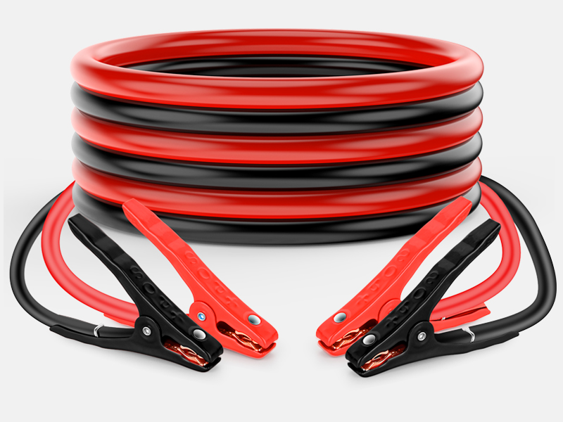
Image 7.1: Illustration of the cable's internal construction, highlighting CCA conductor and PVC insulation.

Image 7.2: Close-up of the jumper cable clamp, detailing its strong spring, copper-coated jaws, and PVC insulation for safety and durability.

Image 7.3: Performance characteristics of the cables, including temperature resistance and weather durability.
8. Warranty and Support
Information regarding product warranty and customer support contact details is not provided within this instruction manual. Please refer to the product packaging or the manufacturer's official website for warranty claims and support inquiries.