1. Introduction
This manual provides detailed instructions for the fushionsea DC 12V-36V 4-Channel Wireless Remote Control Switch, Model AK-C211008. This device is designed for various control applications, including garage doors, motors, industrial control, and household systems. It features a 433MHz RF receiver and two transmitters, offering multiple working modes for flexible operation.

Figure 1: Package contents including the receiver and two remote transmitters.
2. Product Overview
2.1 Receiver Specifications (Model AK-C211008)
- Working Voltage: DC 12V-36V
- Quiescent Current: Less than 6mA
- Working Temperature: -40°C to +80°C
- Receiver Sensitivity: More than -105dBm
- Working Frequency: 433MHz
- Output Voltage: DC and AC (optional)
- Max Load Current: 10A
- Size: 3.74 x 2.44 x 1.1 inches (9.5 x 6.2 x 2.8 cm)

Figure 2: Top view of the receiver board, showing relays and antenna connection.

Figure 3: Key components of the receiver board, including input terminals, indicator light, learning button, and antenna port.
3. Setup and Wiring
The receiver and transmitters are pre-tested before shipping. For initial use, no programming is required if the default mode is suitable. Follow the wiring diagrams carefully for proper installation.
3.1 Wiring Diagrams
Ensure power is disconnected before performing any wiring. Connect the DC 12V-36V power supply to the input terminals labeled '+' and '-' on the receiver board.

Figure 4: Output 12-36V voltage wiring diagram. This configuration provides switched DC voltage to the connected loads.

Figure 5: Output switch signal wiring diagram. This configuration provides a dry contact closure (switch signal) to the connected loads, suitable for controlling external power sources.

Figure 6: Wiring diagram for DC motor control. This setup allows for directional control of a DC motor using two channels.
3.2 Learning and Clearing Method
The receiver can learn different coding remote controls (e.g., 2262, 1527). The number of times the learning button is pressed determines the working mode.
Learning a Remote Transmitter:
- Press the learning button on the receiver board the required number of times for your desired working mode (see Section 4.1). The indicator light will flash and then turn OFF.
- Release your finger from the learning button.
- Press any button on the remote transmitter you wish to pair.
- The indicator light on the receiver will flash three times, indicating successful learning.
Clearing All Learned Codes:
- Press and hold the learning button on the receiver for approximately 8 seconds.
- The indicator light will flash several times and then turn OFF.
- After clearing, press any button on a remote; the relay should not respond, confirming that all codes have been successfully cleared.
4. Operating Modes
The receiver supports six different working modes, which are selected by pressing the learning button a specific number of times during the learning process. Each mode offers distinct control behavior for the relays.
4.1 Mode Selection
- Momentary Mode (Press Learning Button 1 time):
- Relay: Press and hold remote button -> ON; Release remote button -> OFF.
- Toggle Mode (Press Learning Button 2 times):
- Relay: Press remote button -> ON; Press the same button again -> OFF.
- Latched Mode (Press Learning Button 3 times):
- Relay: Press one remote button -> ON; Press another remote button -> OFF. (Typically, one button turns a channel ON, another turns it OFF).
- 2-Channel Momentary + 2-Channel Latched (Press Learning Button 4 times):
- Channels 1 & 2 operate in Momentary mode.
- Channels 3 & 4 operate in Latched mode.
- 2-Channel Momentary + 2-Channel Toggle (Press Learning Button 5 times):
- Channels 1 & 2 operate in Momentary mode.
- Channels 3 & 4 operate in Toggle mode.
- 2-Channel Toggle + 2-Channel Latched (Press Learning Button 6 times):
- Channels 1 & 2 operate in Toggle mode.
- Channels 3 & 4 operate in Latched mode.
Note: The specific assignment of remote buttons to channels depends on the remote transmitter design and the learning sequence.
5. Application Scenarios
This wireless remote control switch is versatile and can be integrated into various systems for remote operation. Common applications include:
- Garage door openers
- Electric gates and sliding doors
- Motor control (e.g., DC motors for blinds, actuators)
- Industrial control systems
- Household lighting and appliance control
- Anti-theft alarm systems
- Lifting equipment
- Access control systems
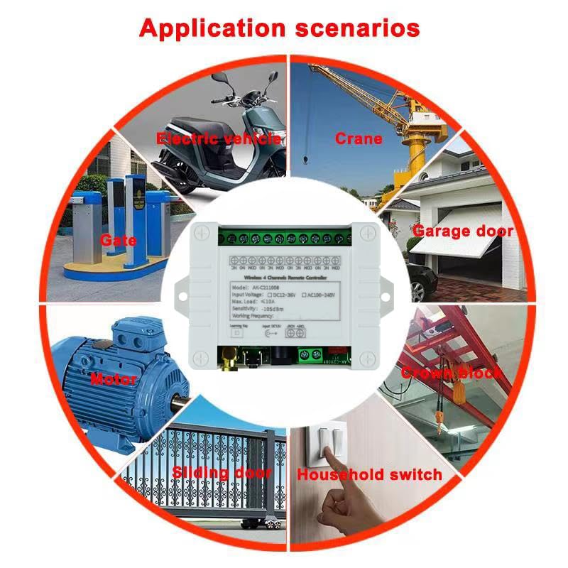
Figure 7: Visual representation of diverse applications, including garage doors, gates, motors, and household switches.
6. Maintenance
The fushionsea wireless remote control switch is designed for reliable operation with minimal maintenance. To ensure longevity and proper function:
- Keep the receiver unit clean and free from dust and moisture.
- Avoid exposing the unit to extreme temperatures outside its specified operating range (-40°C to +80°C).
- Ensure all wiring connections are secure and free from corrosion.
- Replace remote control batteries as needed to maintain signal strength.
7. Troubleshooting
If you encounter issues with your remote control switch, consider the following:
- No Response from Receiver:
- Check power supply to the receiver (DC 12V-36V).
- Ensure remote control batteries are not depleted.
- Verify that the remote is properly paired with the receiver. If unsure, try re-learning the remote (see Section 3.2).
- Confirm that the learning codes have not been accidentally cleared (holding the learning button for 8 seconds clears all codes).
- Limited Range:
- Ensure the antenna on the receiver is properly connected and positioned.
- Minimize obstacles between the remote and receiver. The maximum range is 10-30 meters without obstruction.
- Check for sources of RF interference in the vicinity.
- Incorrect Relay Behavior:
- Verify that the receiver is programmed to the correct working mode (Momentary, Toggle, Latched, etc.) for your application (see Section 4.1). If not, clear existing codes and re-learn the remote in the desired mode.
- Review wiring connections according to the appropriate diagram (Figures 4, 5, 6).
8. Warranty and Support
For warranty information and technical support, please refer to the product packaging or contact your retailer. Keep your purchase receipt for warranty claims.


