
1. Product Overview
The DMK Relfar FWH20-ES10A is an advanced handheld laser welding head designed for precision welding applications. It integrates intelligent dual swing energy storage, a 5-in-1 function, and a double wire feed system to deliver efficient and consistent welding performance. This device is compatible with QBH fiber interfaces, offering flexibility in laser source connections.

Figure 1: Overview of the Relfar Handheld Laser Welding Head (FWH30 series), highlighting intelligent dual swing, energy storage, 5-in-1 function, and single/double wire feed capabilities.
The FWH20-ES10A model is specifically equipped for energy storage applications, providing precise control over the welding process with an adjustable spot range of 0-5mm.
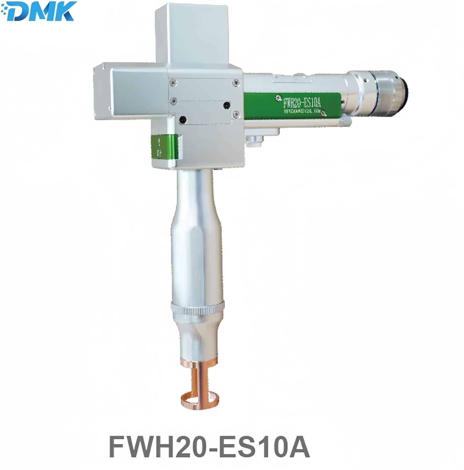
Figure 2: The DMK Relfar FWH20-ES10A Handheld Laser Welding Head.
2. Key Features
- Intelligent Dual Swing Energy Storage: Optimized for efficiency, this welding head features dual swing energy storage for enhanced welding performance and stability.
- 5-in-1 Function Laser Weld Gun: A multifunctional design that caters to diverse welding needs, offering versatility in various applications.
- Double Wire Feed System: Ensures consistent wire feeding during operation, contributing to stable and high-quality welds.
- Fiber Interface QBH Compatibility: The welding head is compatible with QBH fiber interfaces, providing flexible options for laser source connections.
- Adjustable Spot Range: Offers precise control over the welding process with an adjustable spot range of 0-5mm.
3. Technical Specifications
| Specification | Detail |
|---|---|
| Manufacturer | DMK |
| Item Model Number | Handheld Laser Welding Head (FWH20-ES10A) |
| Color/Variant | Fwh20-es10a |
| Power Source | Handheld Laser Welding Head (requires external laser source) |
| Weight | 0.9kg (Head only) |
| Adjustable Spot Range | 0-5mm |
| Fiber Interface | QBH |
4. Setup and Installation
4.1 Unpacking and Component Check
Carefully unpack all components from the packaging. Verify that all items listed in the package contents are present and undamaged. The standard package includes the Relfar Handheld Laser Welding Head and various accessories.

Figure 3: Example of accessories included with the Relfar Handheld Laser Welding Head, showing control unit, power supply, cables, and welding head.
4.2 Connecting the Welding Head
- Ensure the laser source and control unit are powered off before making any connections.
- Connect the QBH fiber interface of the welding head to the compatible laser source. Ensure a secure and clean connection to prevent power loss or damage.
- Connect the control signal cables from the welding head to the main control system. Refer to the "Control signal connection" diagram for proper wiring.
- If using the double wire feed system, connect the wire feeder unit to the welding head and ensure the welding wire is correctly loaded.
- Connect the power supply to the control unit and then to a suitable power outlet.
- Perform a visual inspection of all connections to ensure they are tight and correctly seated.

Figure 4: Diagram illustrating the control signal connections for the handheld welding system. (Note: This image also contains lens replacement diagrams, but the relevant part for setup is the control signal connection.)
5. Operating Instructions
5.1 Safety Precautions
- Always wear appropriate laser safety glasses and protective clothing when operating the laser welding head.
- Ensure the welding area is clear of flammable materials and personnel not involved in the operation.
- Never point the laser beam at people or animals.
- Follow all local safety regulations and guidelines for laser equipment operation.
5.2 Basic Operation
- Power on the laser source and the control unit. Allow the system to initialize.
- Select the desired welding mode and parameters on the control unit. The 5-in-1 function allows for various welding tasks.
- Adjust the spot range (0-5mm) as required for the specific welding application. This can typically be done via the control unit or a mechanism on the welding head itself.
- Position the welding head over the workpiece, ensuring proper standoff distance.
- Initiate the laser beam according to the control unit's instructions.
- Guide the welding head along the weld path. The dual swing energy storage system helps maintain a stable and consistent weld pool.
- If using the double wire feed, ensure the wire is feeding smoothly into the weld pool.
- Upon completion, deactivate the laser beam and power down the system.
6. Maintenance
Regular maintenance is crucial for ensuring the longevity and optimal performance of your Relfar Handheld Laser Welding Head. Always power off and disconnect the device before performing any maintenance.
6.1 Lens Replacement
The welding head contains several optical lenses that may require periodic cleaning or replacement due to wear or damage. Refer to the diagram below for the replacement procedures.
Figure 5: Detailed diagrams for replacing the collimating lens, focusing lens, and protective lens.
6.1.1 Replace the Collimating Lens
- Unscrew the cap pressing.
- Carefully remove the collimating drawer module.
- Use an M2.5 internal hexagon screw to loosen the lens retaining ring.
- Replace the D16*F30 collimation lens, ensuring the surface which is more convex faces upward.
- Reassemble in reverse order, ensuring the 16.5*2*2.3 elastic sealing ring is correctly seated.
6.1.2 Replace the Focusing Lens
- Unscrew the cap pressing.
- Carefully remove the focus drawer module.
- Use an M2.5 internal hexagon screw to loosen the lens retaining ring.
- Replace the D20*F200 focus lens, ensuring the surface which is flatter faces downward.
- Reassemble in reverse order, ensuring the 20.5*16*2.3 elastic sealing ring is correctly seated.
6.1.3 Replace the Protective Lens
- Unscrew the gland (02).
- Carefully draw out the drawer handle module 1 horizontally.
- Remove the D20*2 protective glass (01).
- Replace with a new protective lens.
- Reinsert the drawer handle module 1 and secure the gland (02).
6.2 General Cleaning
- Regularly clean the exterior of the welding head with a soft, dry cloth.
- Ensure all optical components are kept clean and free from dust, debris, and welding spatter. Use specialized optical cleaning solutions and wipes if necessary.
- Inspect cables and connections for any signs of wear or damage.
7. Troubleshooting
This section provides general guidance for common issues. For complex problems, contact technical support.
| Problem | Possible Cause | Solution |
|---|---|---|
| No Laser Output | Power not connected, emergency stop engaged, fiber optic cable damaged, laser source fault. | Check all power connections. Release emergency stop. Inspect fiber optic cable for damage. Consult laser source manual or contact support. |
| Poor Weld Quality | Incorrect welding parameters, dirty lenses, improper wire feed, incorrect standoff distance. | Adjust welding parameters (power, speed, spot size). Clean or replace optical lenses. Check wire feed mechanism and wire quality. Adjust standoff distance. |
| Wire Feed Issues | Wire tangled, feeder motor fault, incorrect wire tension, clogged nozzle. | Untangle wire. Check feeder motor connection. Adjust wire tension. Clean or replace nozzle. |
| Overheating | Insufficient cooling, prolonged operation at high power. | Ensure proper ventilation. Allow the unit to cool down. Reduce operating power or duration. Check cooling system if applicable. |
8. Warranty and Support
DMK products are manufactured to high-quality standards. For warranty information, please refer to the warranty card included with your product or visit the official DMK website. Keep your purchase receipt as proof of purchase.
For technical support, service, or spare parts, please contact DMK customer service through the contact information provided in your product documentation or on the official DMK website. When contacting support, please have your product model number (FWH20-ES10A) and serial number ready.
DMK Laser Official Store: Visit DMK Laser Store on Amazon