
1. Introduction
This manual provides detailed instructions for the installation, operation, and maintenance of your STINGER Audio MT20001 Monoblock Class D Car Amplifier. The MT20001 is designed to deliver high-efficiency power for subwoofer systems in car audio applications, ensuring optimal sound quality. Please read this manual thoroughly before installation and use to ensure proper function and safety.
2. Safety Information
Always observe the following safety precautions to prevent injury or damage to the amplifier or vehicle:
- Disconnect Vehicle Battery: Before beginning any installation, disconnect the vehicle's negative battery terminal to prevent electrical shorts.
- Professional Installation Recommended: If you are unsure about the installation process, consult a qualified car audio professional.
- Proper Wiring: Use appropriate gauge wiring as specified in this manual. Incorrect wiring can lead to overheating, fire, or damage to components.
- Ventilation: Ensure the amplifier is mounted in a location with adequate airflow to prevent overheating. Do not block cooling fins.
- Secure Mounting: Mount the amplifier securely to prevent it from coming loose during vehicle operation, which could cause injury or damage.
- Avoid Moisture: Do not expose the amplifier to moisture or water. This product is not waterproof.
- Fuse Protection: Always use the correct fuse rating as specified. Never replace a fuse with one of a higher rating.
3. Package Contents
Verify that all items are present in your package:
- STINGER Audio MT20001 Monoblock Class D Amplifier
- Remote Subwoofer Level Control with cable
- STINGER 4-Gauge Copper Amplifier Wiring Kit, including:
- 17FT Translucent Blue Power Wire
- 3FT Translucent Silver Ground Wire
- 17FT Translucent Blue Twisted Pair RCA interconnects
- 16FT Blue Remote Turn-on Wire
- 20FT Translucent Speaker Wire
- 3FT Black flex loom tubing
- 1pc Mini-ANL/AFS Fuseholder & Fuse
- Mounting hardware (screws)
- User Manual (this document)

Image: STINGER 1200W Amplifier Wiring Kit packaging, showing the various cables and fuse holder included.
4. Product Features
The STINGER Audio MT20001 amplifier incorporates advanced design and technology for superior performance:
- Digital Class-D Monoblock Design: High efficiency with a compact footprint, optimized for subwoofer applications.
- Robust Unregulated Power Supplies: Utilizes advanced pulse width modulator integrated circuits for improved performance and efficiency.
- Direct Insert Terminals: Features 0/1 Gauge Power and 8 Gauge Speaker direct insert terminals for secure connections.
- Wide Frequency Response: 10Hz-180Hz, suitable for deep bass reproduction.
- Remote Subwoofer Level Control: Included for convenient bass level adjustments.
- Precision Metal Potentiometers: For accurate tuning of audio settings.
- Designed for 1 Ohm Load: Capable of driving demanding subwoofer configurations.

Image: Top view of the STINGER MT-2000.1 amplifier, with text overlays indicating features such as small footprint, 2000W @ 1 Ohm, direct insert terminals, 0/1 gauge power, 8 gauge speaker, 10Hz-180Hz frequency response, and included bass knob.

Image: STINGER MT-2000.1 amplifier, labeled as Class-D Mono Block, with icons and text indicating it's designed for 1 Ohm load, has a small and compact design, features 0/1 Gauge Power Terminal, has a Bridged RMS Rating of 3,800W / 2 Ohm Minimum, and an Operating voltage of 9V to 16V.
5. Setup and Installation
Careful installation is crucial for optimal performance and safety. Follow these steps for proper setup.
5.1 Component Identification
Familiarize yourself with the amplifier's input and output terminals and control panel:

Image: Rear view of the STINGER MT-2000.1 amplifier showing the control panel. Labels include PRT (Protection Indicator), PWR (Power Indicator), REMOTE port (for bass knob), INPUT RCA (L/R), BRIDGE IN RCA, GAIN knob (Min/Max), LPF knob (40Hz-180Hz), SUBSONIC knob (OFF/50Hz), FREQ knob (30Hz/80Hz), BOOST knob (0dB/12dB), and INPUT BRIDGE OUT RCA.
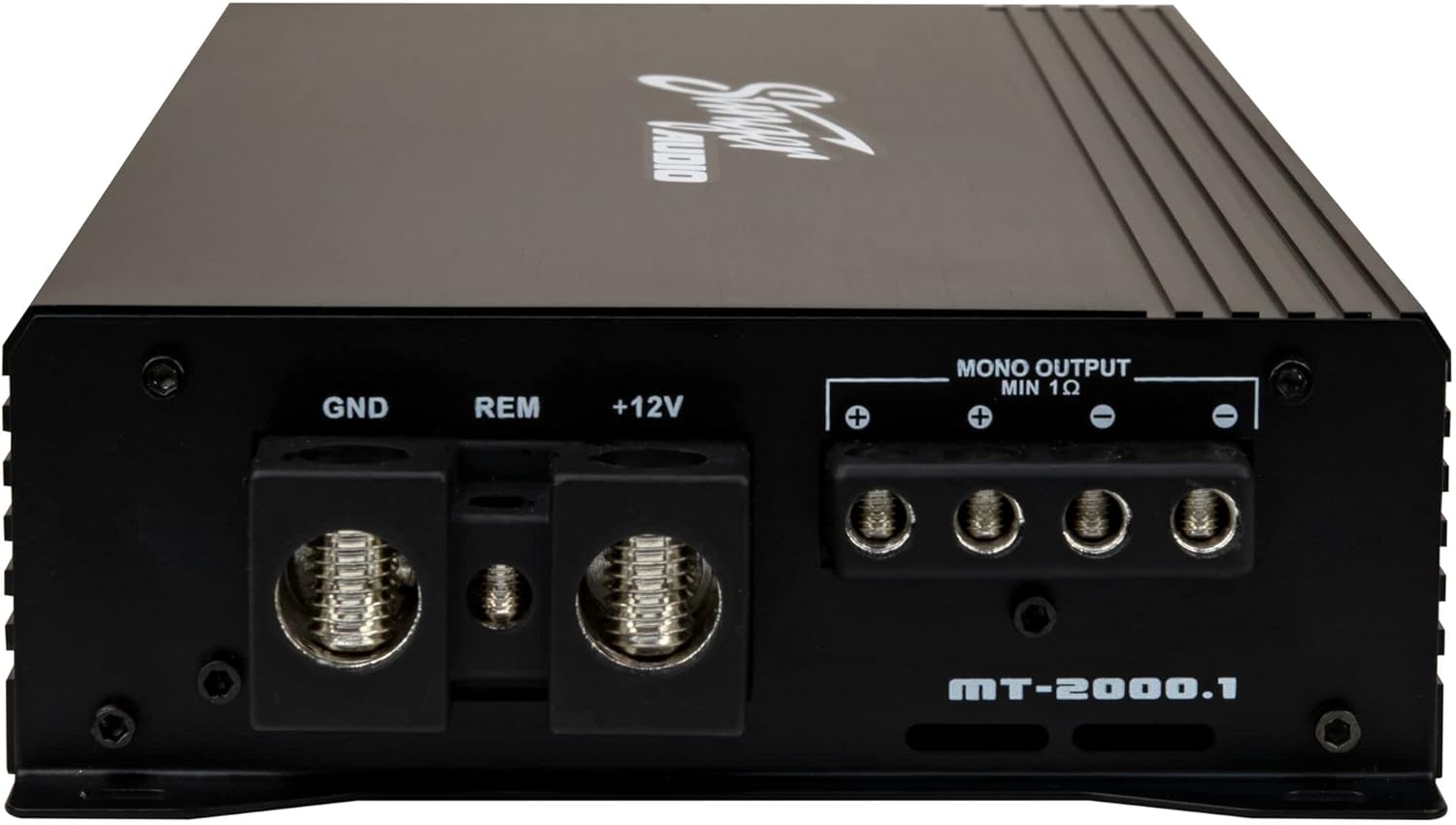
Image: Rear view of the STINGER MT-2000.1 amplifier showing the power and speaker terminals. Labels include GND (Ground), REM (Remote Turn-on), +12V (Power), and MONO OUTPUT MIN 1 Ohm speaker terminals (+ and -).
5.2 Wiring Connections
Follow these steps for secure and correct wiring:
- Power Wire (+12V): Connect the 17FT Translucent Blue Power Wire from the vehicle's positive battery terminal (via the Mini-ANL/AFS Fuseholder & Fuse, installed within 18 inches of the battery) to the +12V terminal on the amplifier. Ensure a secure, crimped connection.
- Ground Wire (GND): Connect the 3FT Translucent Silver Ground Wire from the GND terminal on the amplifier to a clean, unpainted metal surface on the vehicle chassis. Ensure a solid, low-resistance connection.
- Remote Turn-on Wire (REM): Connect the 16FT Blue Remote Turn-on Wire from the REM terminal on the amplifier to the remote output of your head unit or other switched 12V source. This wire turns the amplifier on and off with your head unit.
- RCA Input: Connect the 17FT Translucent Blue Twisted Pair RCA interconnects from the RCA output of your head unit to the INPUT RCA terminals (L/R) on the amplifier. For bridged input, use the BRIDGE IN RCA terminal.
- Speaker Output: Connect your subwoofer(s) to the MONO OUTPUT MIN 1 Ohm terminals on the amplifier using the 20FT Translucent Speaker Wire. Observe correct polarity (+ to + and - to -). Ensure the total impedance of your subwoofer(s) is 1 Ohm or higher.
- Remote Subwoofer Level Control: Plug the included remote bass knob into the REMOTE port on the amplifier.
5.3 Mounting
Choose a mounting location that provides adequate ventilation and is secure. Avoid mounting the amplifier directly to carpet or in enclosed spaces without airflow. Use the provided mounting hardware to firmly attach the amplifier to a solid surface in your vehicle.
6. Operating Instructions
Once installed, adjust the amplifier settings for optimal sound performance.
6.1 Adjusting Controls
- GAIN (Input Level): This control matches the amplifier's input sensitivity to the output of your head unit. Start with the gain at minimum (fully counter-clockwise). Play a familiar track at about 75% of your head unit's maximum volume. Slowly increase the gain until you hear distortion, then back off slightly.
- LPF (Low Pass Filter): This filter allows only frequencies below the set point to pass through to the subwoofer. Adjust this knob (40Hz-180Hz) to blend the subwoofer's output with your main speakers. A common starting point is 80Hz.
- SUBSONIC: This high-pass filter removes extremely low frequencies that are below the audible range or harmful to your subwoofer. Set it to OFF or 50Hz, depending on your subwoofer's capabilities and enclosure tuning.
- FREQ (Bass EQ Frequency): This knob (30Hz/80Hz) selects the center frequency for the Bass BOOST.
- BOOST (Bass EQ Level): This control (0dB/12dB) increases the output at the selected FREQ. Use sparingly to avoid distortion and potential damage to your subwoofer.
6.2 Remote Subwoofer Level Control
The included remote level control allows you to conveniently adjust the subwoofer output level from your driving position. This control only adjusts the output level and does not affect the amplifier's gain setting.

Image: The STINGER remote subwoofer level control, a small black box with a rotary knob labeled 'MIN' to 'MAX', connected by a cable.
7. Maintenance
The STINGER MT20001 amplifier requires minimal maintenance to ensure long-term performance.
- Cleaning: Periodically wipe the amplifier's exterior with a soft, dry cloth. Do not use harsh chemicals or abrasive cleaners.
- Check Connections: Annually, inspect all power, ground, remote, RCA, and speaker connections to ensure they are secure and free from corrosion. Loose connections can cause performance issues or damage.
- Ventilation: Ensure that the amplifier's cooling fins remain clear of obstructions to maintain proper heat dissipation.
8. Troubleshooting
If you experience problems with your amplifier, refer to the following table for common issues and solutions:
| Problem | Possible Cause | Solution |
|---|---|---|
| No Power (PWR LED off) | Blown fuse, loose power/ground/remote wire, no 12V at battery. | Check fuse, verify all power connections, test battery voltage. |
| Protection Mode (PRT LED on) | Overheating, speaker short circuit, low impedance load. | Ensure proper ventilation, check speaker wiring for shorts, verify speaker impedance is 1 Ohm or higher. Allow amplifier to cool. |
| No Sound Output | No RCA signal, gain too low, speaker wires disconnected, head unit off. | Check RCA connections, adjust gain, verify speaker wiring, ensure head unit is on and playing audio. |
| Distorted Sound | Gain set too high, poor ground connection, damaged speaker, incorrect LPF/BOOST settings. | Reduce gain, check ground connection, inspect speaker, adjust LPF/BOOST settings. |
| Amplifier Overheats | Insufficient ventilation, impedance too low, gain too high. | Relocate amplifier for better airflow, verify speaker impedance, reduce gain. |
9. Specifications
Detailed technical specifications for the STINGER Audio MT20001 Monoblock Class D Car Amplifier:
| Specification | Value |
|---|---|
| Model Name | MT20001 |
| Material | Metal |
| Speaker Type | Subwoofer |
| Speaker Maximum Output Power | 2000 Watts |
| Audio Output Mode | Mono |
| Connectivity Technology | RCA |
| Subwoofer Connectivity Technology | Wired |
| Control Method | Remote |
| Power Source | Corded Electric |
| Operating Voltage | 9V to 16V |
| Minimum Impedance | 1 Ohm |
| Mounting Type | Flush Mount |
| Is Waterproof | FALSE |
| Item Model Number | MT20001 |
| Date First Available | August 20, 2024 |

Image: STINGER MT-2000.1 amplifier with dimensions indicated: 12.16 inches (309 mm) length, 6.1 inches (155 mm) width, and 2.09 inches (53 mm) height.
10. Warranty and Support
STINGER products are designed for reliability and performance. For specific warranty information, please refer to the warranty card included with your product or visit the official STINGER website. If you encounter any issues not covered in this manual or require technical assistance, please contact STINGER customer support through their official channels.
STINGER Customer Support: Refer to your product packaging or the official STINGER website for the most current contact information.


