
1. Introduction
The JKBMS Smart Battery Management System (BMS) model JK-BD6A24S10P is designed to protect and optimize the performance of lithium battery packs. This device is compatible with Li-ion, LiFePO4, and LTO battery chemistries, supporting configurations from 8S to 24S. It features a 100A continuous discharge current, 0.6A active balance, built-in Bluetooth for mobile app connectivity, and an RS485 communication interface. This manual provides essential information for the safe and effective installation, operation, and maintenance of your JKBMS Smart BMS.

Image 1: JKBMS Smart BMS JK-BD6A24S10P unit. This image displays the main unit of the JKBMS Smart BMS, highlighting its compact design and connection points for battery terminals (B- and P-) and balance wires.
2. Product Features
The JKBMS Smart BMS JK-BD6A24S10P incorporates several features to ensure battery safety and longevity:
- Enhanced Safety Protection: Provides comprehensive protection against overcharging, over-discharging, overcurrent, short circuits, and extreme temperatures.
- Active Equalization: Features a 0.6A active balance current to efficiently equalize cell voltages, extending battery life and enhancing performance.
- Bluetooth Connectivity: Allows for easy management and monitoring of battery status, settings adjustments, and control of charging/discharging via a dedicated mobile application for Android and iOS devices.
- Wide Application Compatibility: Supports Li-ion, LiFePO4, and LTO battery types, suitable for various applications including electric vehicles, energy storage systems, and portable power solutions.
- RS485 Communication: Includes an RS485 interface for integration with external systems, such as inverters (RS485 converter not included).

Image 2: Diagram illustrating the eight security protection features. This graphic visually represents the various protection mechanisms of the BMS, including equalization, overcharge, short circuit, over-discharge, overcurrent, over-temperature, PCB protection, and disconnection protection.
3. Package Contents
Upon opening the package, verify that all the following items are included:
- Smart BMS (JK-BD6A24S10P) x 1
- Balance Wires (70cm) x 1
- Switch (50cm) x 1
- NTC Temperature Sensor (40cm) x 1
- Operation Manual x 1
Please note: An RS485 converter is not included in this package and must be acquired separately if needed for your application.
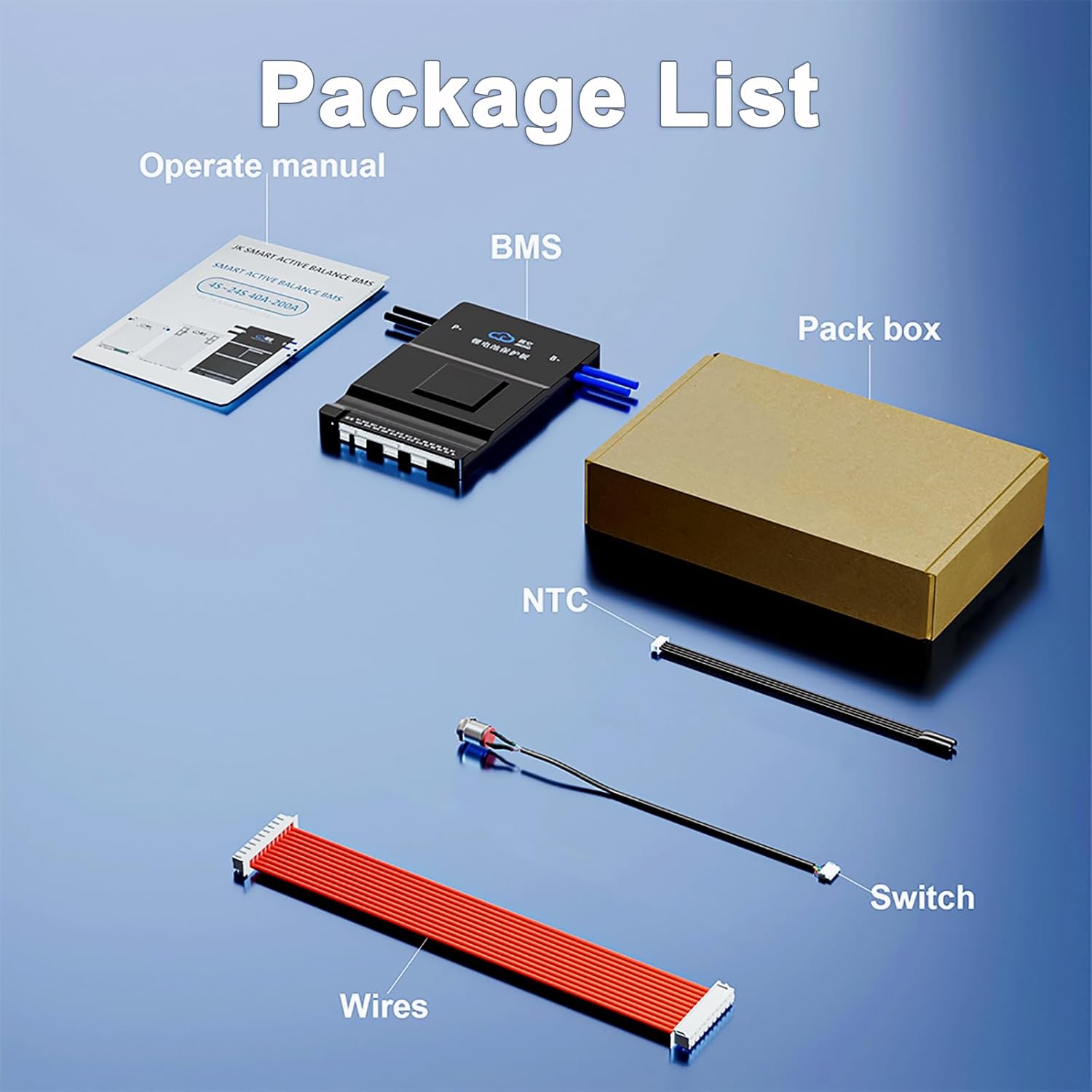
Image 3: Visual representation of the package contents. This image shows the Smart BMS unit, balance wires, switch, NTC temperature sensor, and the operation manual, as they would appear when unboxed.
4. Specifications
Key technical specifications for the JKBMS Smart BMS JK-BD6A24S10P:
| Parameter | Value |
|---|---|
| Model | JK-BD6A24S10P |
| Supported Cell Count | 8S-24S |
| Balance Current | 0.6A |
| Continuous Discharge Current | 100A |
| Maximum Instantaneous Current | 200A |
| Communication | Bluetooth (standard), CAN/RS485 (optional) |
| Overcharge Protection Voltage | 1.2-4.4V (adjustable) |
| Overdischarge Protection Voltage | 1.2-4.4V (adjustable) |
| Single Cell Battery Collection Range | 1V-5V |
| Voltage Acquisition Accuracy | ±3mV |
| Power Requirements | 20V-100V |
| Dimensions (L x W x H) | 6.38 x 4.02 x 0.8 inches (162 x 102 x 20.4 mm) |
| Item Weight | 12.8 ounces (Approx. 360g) |

Image 4: Detailed specifications table for the JKBMS Smart BMS. This image provides a clear overview of the technical parameters, including model number, balance current, continuous discharge current, and various protection voltage ranges.
5. Safety Precautions
Adhere to the following safety guidelines during installation and operation:
- Always disconnect the battery pack from any power source before installing or servicing the BMS.
- Ensure correct polarity for all connections. Incorrect wiring can damage the BMS, battery, or connected equipment.
- Wear appropriate personal protective equipment (PPE), including insulated gloves and eye protection.
- Avoid short-circuiting battery terminals or BMS connection points.
- Install the BMS in a dry, well-ventilated area, away from flammable materials and direct sunlight.
- Do not attempt to open or modify the BMS unit. Refer all repairs to qualified personnel.
- Verify that the BMS model is compatible with your battery pack's cell count and chemistry (Li-ion, LiFePO4, LTO).
6. Installation and Wiring
Proper installation and wiring are crucial for the correct functioning of the BMS. Follow these steps carefully:
- Prepare the Battery Pack: Ensure all individual cells in your battery pack are balanced and at a safe voltage level before connecting the BMS.
- Connect Balance Wires: Connect the provided balance wires to each cell's positive terminal, starting from B1 (first cell positive) up to the highest cell positive (e.g., B24 for a 24S pack). Ensure the wires are connected in the correct sequence.
- Connect Main Battery Terminals: Connect the main negative terminal of the battery pack to the B- terminal on the BMS.
- Connect Load/Charger: Connect the negative terminal of your load and charger to the P- terminal on the BMS. The positive terminals of the battery, load, and charger should be connected directly together.
- Connect NTC Temperature Sensor: Attach the NTC temperature sensor to a central location on your battery pack to accurately monitor its temperature.
- Connect Switch: Connect the provided switch to the designated port on the BMS. This switch can be used to power on/off the BMS.
- Verify Connections: Double-check all wiring for correct polarity and secure connections before applying power.

Image 5: Detailed wiring diagram for the JKBMS Smart BMS. This diagram illustrates the connections for the balance wires, main battery terminals (B-), and the common port for load and charger (P-), providing a visual guide for installation.
7. Operation
The JKBMS Smart BMS is primarily operated and monitored via its dedicated mobile application, accessible via Bluetooth.
7.1 Mobile App Connection
- Download the official JKBMS app from your device's app store (Android or iOS).
- Ensure Bluetooth is enabled on your mobile device.
- Open the JKBMS app and search for available BMS devices.
- Select your BMS from the list to establish a connection.
7.2 Monitoring and Settings
Through the app, you can:
- Monitor real-time battery data, including total voltage, individual cell voltages, current, temperature, State of Charge (SOC), and State of Health (SOH).
- Adjust various protection parameters such as overcharge/over-discharge voltage limits, overcurrent thresholds, and temperature limits.
- Control the BMS balance switch and other operational modes.

Image 6: Screenshot of the Smart Bluetooth App interface. This image shows the mobile application displaying real-time battery data, including voltage, current, temperature, and individual cell readings, demonstrating the monitoring capabilities.
8. Application Scenarios
The JKBMS Smart BMS JK-BD6A24S10P is suitable for a wide range of applications requiring robust battery management:
- Electric Sightseeing Cars
- Micro Electric Vehicles (EVs)
- Electric Cargo Tricycles
- E-bikes and Electric Scooters
- RV Energy Storage Systems
- Home Energy Storage Cabinets
- Portable Power Banks
- Industrial Drones
- Power Tools
- Forklifts
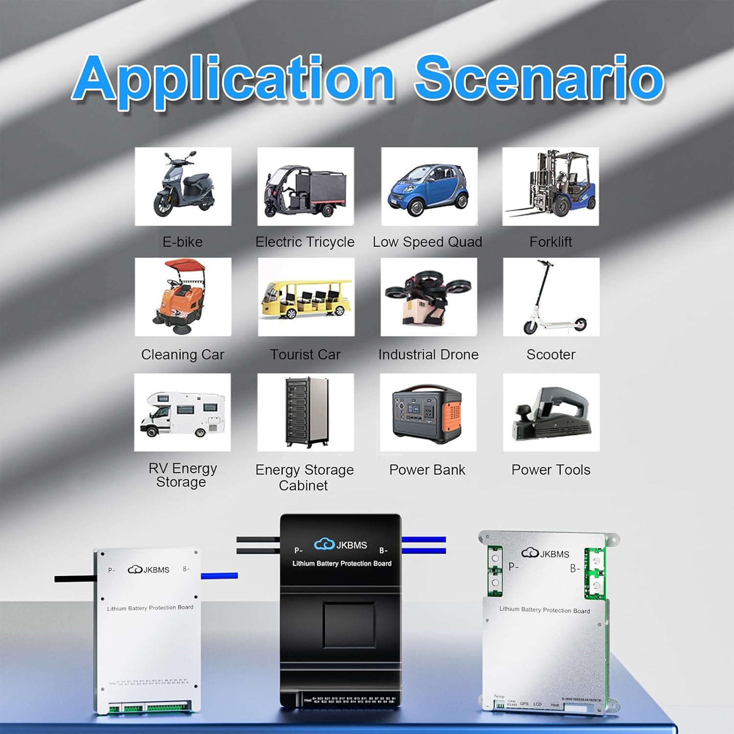
Image 7: Collage depicting various application scenarios. This image showcases different vehicles and systems where the JKBMS Smart BMS can be effectively utilized, such as e-bikes, electric tricycles, forklifts, and RVs.
9. Maintenance
To ensure optimal performance and longevity of your JKBMS Smart BMS and battery pack, consider the following maintenance practices:
- Regular Monitoring: Periodically check battery parameters via the mobile app to identify any anomalies early.
- Keep Connections Secure: Ensure all wiring connections remain tight and free from corrosion. Loose connections can lead to resistance and heat buildup.
- Cleanliness: Keep the BMS unit clean and free from dust and debris. Avoid exposing it to excessive moisture.
- Temperature Management: Operate the battery and BMS within their specified temperature ranges. Extreme temperatures can degrade performance and lifespan.
- Firmware Updates: Check for and apply any available firmware updates for the BMS via the mobile app to ensure you have the latest features and bug fixes.
10. Troubleshooting
This section addresses common issues you might encounter with your JKBMS Smart BMS.
10.1 BMS Not Connecting via Bluetooth
- Ensure the BMS is powered on.
- Verify Bluetooth is enabled on your mobile device.
- Move closer to the BMS to improve signal strength.
- Restart the mobile app or your mobile device.
- Check if the BMS has been paired with another device.
10.2 Battery Cells Unbalanced
- Ensure the active balance function is enabled in the mobile app settings.
- Allow sufficient time for the active balancing to occur, especially if the cells were significantly out of balance.
- Verify all balance wires are correctly and securely connected to each cell.
10.3 Heater Function Not Activating (if applicable)
For BMS models with a heating function, activation typically depends on specific conditions:
- Condition 1: Battery temperature is below the configured charging low-temperature protection threshold.
- Condition 2 (Manual): Heating is manually activated via the APP, without checking the charger status. This will consume battery power.
- Condition 3 (Automatic): The charger is detected as being plugged in, and Condition 1 is met. This function is hardware-dependent.
Ensure your heating film specifications (voltage, resistance, wattage) are compatible with the BMS output.
10.4 RS485/CAN Communication Issues
- Verify that you are using the correct RS485 converter (not included) and that its drivers are properly installed.
- For UART/serial communication via the 'GPS port', ensure only the middle two wires are used (TX and RX), and the ground is not connected from the adapter. Use a 3.3V adapter.
- Confirm the correct communication protocol settings within the BMS app (e.g., selecting 'GPS' for UART in advanced settings).
- Note that CAN versions may support specific JK BMS protocols, which might not be compatible with third-party equipment like Victron without additional interfaces or specific configurations.
11. Warranty and Support
JKBMS provides a 1-year support period for this product. If you encounter any questions, concerns, or require technical assistance, please contact JKBMS customer support through your order page. We are committed to ensuring your satisfaction and providing timely assistance.


