
1. Introduction
The Voswitch JL410 Grab Handle 4-Switch Panel System is designed to provide a robust and integrated power distribution solution for Jeep Wrangler JL and Gladiator JT models from 2024 onwards. This system replaces the factory A-pillar grab handle trim with a sleek, minimalist 4-switch interface, offering convenient control for your auxiliary accessories.
Key features include a 100A total capacity power module with four 30A outputs, green backlighting with an orange active indicator, memory dimming, and an IP66 waterproof rating for both the switch panel and power module. An integrated Low Voltage Disconnect (LVD) protects your vehicle's battery from excessive discharge.
2. Safety Information
- Always disconnect the vehicle's battery before beginning any electrical installation to prevent electrical shock or damage.
- Ensure all wiring connections are secure and properly insulated to avoid short circuits.
- Do not exceed the maximum current ratings for the power module (100A total) or individual outputs (30A each).
- Route all cables away from moving parts, sharp edges, and high-heat areas.
- Verify that the installation does not interfere with the operation of airbags or other safety systems.
- If you are unsure about any part of the installation process, consult a qualified professional.
3. Package Contents
Verify that all components listed below are included in your package:

Image: Voswitch JL410 Package Contents
- Switch Panel
- Power Module
- Control Wire (13-foot communication cable)
- Add-a-Circuit Fuse Tap
- Zip Ties
- Instruction Manual (Detailed Installation Guide)
- Mounting Hardware
- Spare Main Fuse
- Terminals
4. Product Overview
The Voswitch JL410 system integrates seamlessly into your Jeep's interior and electrical system, providing centralized control for auxiliary devices.

Image: Voswitch JL410 System Components
4.1 Switch Panel
- Design: Patented A-pillar mount, replacing the factory grab handle trim.
- Controls: Four individual switches for auxiliary accessories.
- Lighting: Green backlight for easy identification, turning orange when a switch is active.
- Dimming: Memory dimming function (100% to 10% brightness).
4.2 Power Module
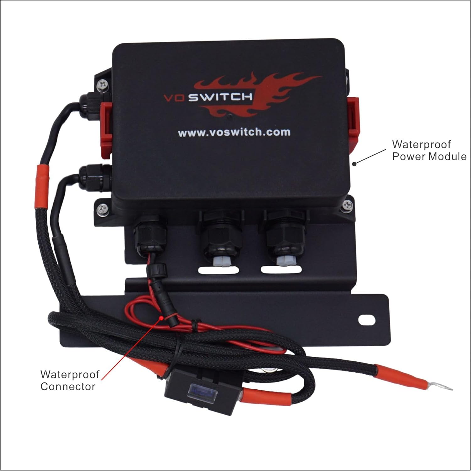
Image: Voswitch JL410 Power Module Details
- Capacity: 100A total capacity.
- Outputs: Four dedicated high-performance outputs, each rated at 30A.
- Durability: IP66 waterproof rating, designed for harsh under-hood temperatures (-40°C to 125°C).
- Protection: Integrated Low Voltage Disconnect (LVD) to prevent battery drainage.
5. Setup and Installation
The Voswitch JL410 is designed for a plug-and-play installation. Refer to the detailed installation guide included in your package for specific vehicle wiring diagrams and mounting instructions. The following provides a general overview of the installation steps.

Image: Power Module Installed in Engine Bay
5.1 General Installation Steps
- Disconnect Battery: Before starting, disconnect the negative terminal of your vehicle's battery.
- Mount Power Module: Securely mount the power module in the engine bay using the provided brackets and hardware. Choose a location that is accessible but protected from extreme heat and moving parts.
- Mount Switch Panel: Remove the factory A-pillar grab handle trim. Install the Voswitch JL410 switch panel in its place, ensuring it clicks securely into position.
- Connect Power: Connect the main power cable from the power module to the vehicle's battery, ensuring the in-line fuse is properly installed. Connect the ground wire to a suitable chassis ground point.
- Connect Control Wire: Route the 13-foot communication cable from the power module in the engine bay to the switch panel inside the cabin. Connect both ends securely.
- Connect Accessories: Wire your auxiliary accessories (e.g., LED light bars, air compressors) to the designated output terminals on the power module. Ensure each accessory is properly fused and grounded.
- Reconnect Battery: Once all connections are secure and verified, reconnect the vehicle's negative battery terminal.
- Test System: Turn on your vehicle and test each switch to ensure proper operation of your connected accessories.
Important: Always refer to the detailed installation guide provided in your package for vehicle-specific instructions and diagrams.
6. Operating Instructions
6.1 Basic Operation
- Press any of the four buttons on the switch panel to activate or deactivate the corresponding auxiliary accessory.
- The switch panel features a green backlight for visibility in low light conditions.
- When an accessory is active, the corresponding switch indicator will illuminate orange, providing instant visual confirmation.
6.2 Memory Dimming Function
- The switch panel includes a memory dimming function, allowing you to adjust the backlight brightness from 100% down to 10%.
- Consult the detailed installation guide for specific instructions on how to adjust and save your preferred dimming level.
6.3 Low Voltage Disconnect (LVD)
- The system is equipped with an intelligent Low Voltage Disconnect (LVD) feature to protect your vehicle's battery from excessive discharge.
- If the vehicle's battery voltage drops below a safe operating threshold, the system will automatically shut off power to connected accessories to ensure sufficient power remains to start the engine.
- Power will be restored once the battery voltage returns to a safe level (e.g., after the engine is started or the battery is charged).
7. Maintenance
- Regular Inspection: Periodically inspect all wiring, connections, and mounting points for signs of wear, corrosion, or looseness.
- Cleanliness: Keep the switch panel and power module clean and free of dirt, dust, and debris. Use a soft, damp cloth for cleaning. Avoid harsh chemicals.
- Water Resistance: The power module and switch panel are IP66 rated for water and dust resistance. However, avoid direct high-pressure water sprays on electrical components.
- Fuse Check: If an accessory stops working, check the individual fuse for that output on the power module, as well as the main in-line fuse. Replace blown fuses with ones of the correct amperage.
8. Troubleshooting
| Problem | Possible Cause | Solution |
|---|---|---|
| System has no power / No lights on switch panel. | Main power fuse blown; Loose battery connections; Control wire disconnected. | Check and replace the main in-line fuse. Ensure battery terminals are clean and tight. Verify the 13-foot control wire is securely connected at both ends. |
| An accessory does not turn on. | Individual output fuse blown; Loose accessory wiring; Faulty accessory. | Check and replace the specific output fuse on the power module. Verify the accessory's wiring to the power module and its ground connection. Test the accessory directly if possible. |
| Switch panel backlight is off or dim. | Dimming function set too low; Power issue. | Adjust the dimming level. If still off, check main power connections. |
| Power button blinking when vehicle is off. | Low Voltage Disconnect (LVD) activated; Loose connection. | This typically indicates the LVD has activated to protect your battery. Start the vehicle to recharge the battery. If the issue persists after charging, check all power and ground connections for looseness or corrosion. |
If you encounter issues not covered here or require further assistance, please contact Voswitch customer support.
9. Specifications
| Feature | Detail |
|---|---|
| Model Number | JL410 |
| Total Current Capacity | 100A |
| Output Channels | 4 (each rated at 30A) |
| Switch Panel Backlight | Green (Orange when active) |
| Waterproof Rating | IP66 (Switch Panel & Power Module) |
| Operating Temperature | -40°C to 125°C |
| Compatibility | Jeep Wrangler JL (2024-Current), Jeep Gladiator JT (2024-Current) |
| Control Wire Length | 13 feet |
| Handle Material | Stainless Steel |
| UPC | 717373634236 |
| ASIN | B0D6XLS758 |
10. Warranty Information
For detailed warranty terms and conditions, please refer to the official warranty statement provided with your product or visit the Voswitch official website. Warranty coverage typically includes defects in materials and workmanship under normal use.
11. Customer Support
Should you require technical assistance, have questions regarding installation, or need to report an issue, please contact Voswitch customer support.
- Brand: Voswitch
- Online Store: Visit the Voswitch Store on Amazon
- Contact: Refer to the contact information provided in your product packaging or on the official Voswitch website.