
1. Introduction
This manual provides detailed instructions for the installation, operation, and maintenance of the Aoleaby JK Smart BMS Active Balance Protection Board, model BD6A17S8P. This device is designed to manage and protect LiFePo4 and Li-ion battery systems ranging from 4S to 24S, ensuring optimal performance and extended battery life through active balancing and comprehensive protection features.
2. Safety Information
Read all instructions carefully before installation and operation. Failure to follow safety guidelines can result in damage to the device, battery, or personal injury.
- Ensure all connections are correct and secure before applying power.
- Do not short-circuit the battery terminals.
- Work in a well-ventilated area.
- Use appropriate personal protective equipment (PPE).
- Consult a qualified professional if you are unsure about any installation steps.
- This device is intended for use with LiFePo4 and Li-ion battery types only.
3. Package Contents
Verify that all items are present in the package:
- JK Smart BMS Active Balance Protection Board (BD6A17S8P)
- Sampling Cable (Balance Wires)
- Temperature Sensor
- RS485 Communication Cable (if included)
- LCD Display Cable (if included)
- User Manual (this document)

Image: Contents of the JK Smart BMS package, including the main board, red and black wiring harnesses, and a small brown box.
4. Product Overview
The JK Smart BMS BD6A17S8P is an advanced battery management system designed for optimal battery health and safety. It features active balancing, over-charge/discharge protection, over-current protection, short-circuit protection, and low-temperature charging cutoff.

Image: Front view of the JK Smart BMS board, displaying the "JIKONG" logo, a QR code for APP download, and labels for P- and B- terminals.
For APP download and further information, scan the QR code or visit: http://qr17.cn/BApbC0

Image: Detailed view of the JK Smart BMS BD6A17S8P, outlining its functions: Bluetooth/RS485 communication, 0.6A balance current, support for 8S-17S battery strings, 80A charge/discharge current, dimensions (131*81*18mm), and compatibility with Li-ion/LiFePo4/LTO battery types.
For APP download and further information, scan the QR code or visit: http://qr17.cn/BApbC0

Image: Close-up view of the JK Smart BMS board, indicating connection ports for the Temperature sensor, RS485 communication (by default), and an optional LCD display (by default).

Image: Another view of the JK Smart BMS board, highlighting its robust construction and various connection points.
For APP download and further information, scan the QR code or visit: http://qr17.cn/BApbC0
5. Setup and Wiring
Proper wiring is crucial for the safe and correct operation of the BMS. Follow the diagram carefully.
- Connect the main negative terminal of the battery pack to the B- terminal on the BMS.
- Connect the main positive terminal of the battery pack to the P+ terminal (if applicable, or directly to load/charger positive).
- Connect the sampling cable (balance wires) to each cell's positive terminal, starting from the first cell (B1) up to the last cell (B17 for this model). Ensure the order is correct.
- Connect the load and charger to the P- and P+ terminals as shown in the diagram.
- Connect the temperature sensor to the designated port on the BMS.
- If using RS485 communication or an LCD, connect the respective cables to their ports.
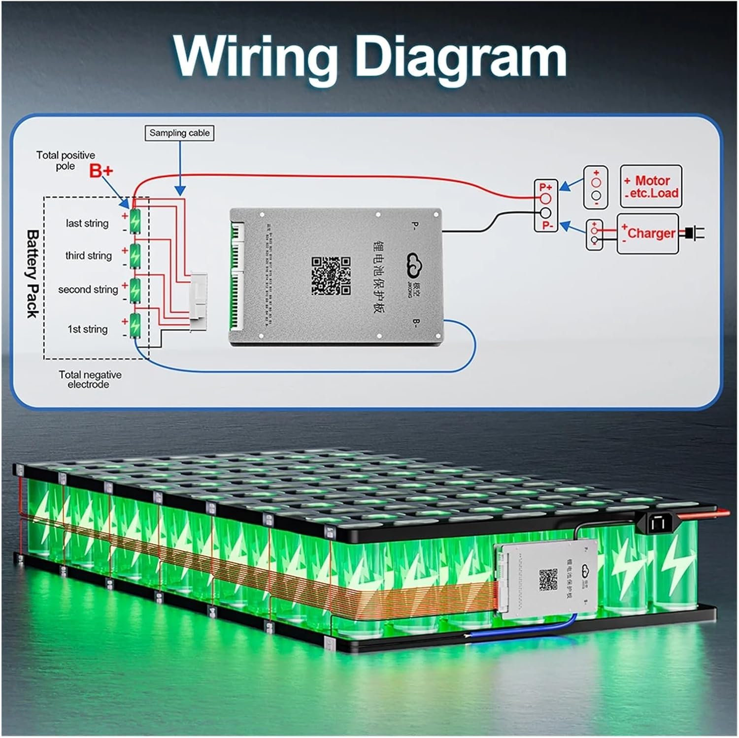
Image: Comprehensive wiring diagram illustrating how to connect the JK Smart BMS to a multi-cell battery pack, including connections for the total positive (B+) and negative (P-) terminals, sampling cables for individual cells, and outputs for motor, load, and charger.
For detailed wiring instructions and APP download, scan the QR code or visit: http://qr17.cn/BApbC0
6. Operating Instructions
6.1 Bluetooth APP Control
The JK Smart BMS features a dedicated mobile application for monitoring and configuring battery parameters.
- Download the "JK BMS" APP by scanning the QR code on the product or visiting the provided link: http://qr17.cn/BApbC0
- Enable Bluetooth on your smartphone.
- Open the JK BMS APP and search for available devices.
- Select your BMS from the list to connect.
- Once connected, you can view real-time battery status, individual cell voltages, temperature, charge/discharge current, and adjust various protection parameters.

Image: The JK Smart BMS board displayed next to a smartphone screen showing the active balance and monitoring features of the associated mobile application.
For APP download and further information, scan the QR code or visit: http://qr17.cn/BApbC0
6.2 RS485 Communication
The RS485 port allows for wired communication with external devices, such as computers or other monitoring systems, for advanced data logging and control. Refer to the technical documentation for the RS485 communication protocol.
7. Maintenance
The JK Smart BMS is designed for reliable operation with minimal maintenance.
- Regularly check all wiring connections for tightness and corrosion.
- Keep the BMS clean and free from dust and moisture.
- Monitor battery cell voltages via the APP to ensure active balancing is functioning correctly.
- Avoid exposing the BMS to extreme temperatures or direct sunlight.
8. Troubleshooting
If you encounter issues, refer to the following common problems and solutions:
- BMS not powering on: Check main battery connections (B-, P+). Ensure the battery pack voltage is within the supported range.
- Bluetooth connection issues: Ensure Bluetooth is enabled on your phone. Restart the APP and try reconnecting. Verify the BMS is powered.
- Cell voltage imbalance: The active balancing feature works continuously. Allow time for balancing to occur. If imbalance persists, check individual cell connections and the balance wires.
- Over-current/Short-circuit protection triggered: Disconnect the load immediately. Identify and resolve the cause of the over-current or short-circuit. The BMS will typically reset automatically once the fault is cleared.
- Low-temperature charging cutoff: This is a safety feature. Charging will resume automatically when the battery temperature rises above the set threshold.
For further assistance, contact Aoleaby customer support.
9. Specifications
The following table details the specifications for the JK Smart BMS BD6A17S8P model.
| Feature | Specification |
|---|---|
| Model | BD6A17S8P |
| Supported Battery Types | Li-ion, LiFePo4, LTO |
| Supported String Count | 8S-17S |
| Active Balance Current | 0.6A |
| Charge Current | 80A |
| Discharge Current | 80A |
| Communication | Bluetooth APP, RS485 |
| Protection Features | Over-charge, Over-discharge, Over-current, Short-circuit, Low-temperature charging cutoff |
| Dimensions | 131 x 81 x 18 mm |
| Item Weight | 2.2 pounds (approx. 1 kg) |
For a comprehensive list of product specifications across various models, refer to the detailed specification table provided in the product images.

Image: A detailed table outlining product specifications for multiple JK Smart BMS models, including parameters like item number, supported string count, active balance current, continuous charge/discharge current, and other interface options. The BD6A17S8P model is included in this table.
10. Warranty and Support
For warranty information and technical support, please contact Aoleaby customer service through your purchase platform or refer to the official product website. Keep your purchase receipt as proof of purchase.
Manufacturer: Aoleaby
Item model number: Aoleaby (Note: The specific model for this manual is BD6A17S8P)