
1. Introduction
The GuliTech MS8301A is a compact and reliable digital multimeter designed for measuring AC/DC voltage, DC current, resistance, diode, and continuity. It also features a battery test function and data hold capability, making it suitable for various electrical and electronic testing applications. This manual provides essential information for safe and effective operation of your device.
2. Safety Information
Always observe basic safety precautions when using this multimeter to avoid personal injury or damage to the meter or equipment under test. Read all instructions before use.
- Do not exceed the maximum input limits for any function.
- Use extreme caution when working with voltages above 60V DC or 30V AC RMS.
- Ensure the test leads are in good condition and properly seated.
- Never connect the meter to a voltage source when the rotary switch is in the current, resistance, diode, or continuity position.
- Always turn off power to the circuit and discharge all high-voltage capacitors before performing resistance, diode, or continuity tests.
- Replace the battery immediately when the low battery indicator appears.
3. Product Features
The GuliTech MS8301A Digital Multimeter offers the following key features:
- 2000 Counts Display: Provides clear and precise readings.
- Data Hold Function: Allows you to freeze the displayed reading for convenient recording.
- 1.5V/9V Battery Tester: Integrated function for quick battery status checks.
- Compact Design: Product dimensions are approximately 150mm x 74mm x 48mm (5.9" x 2.9" x 1.7").
- Lightweight: Weighs approximately 220g (0.48lb).

Image: This image displays the key features of the MS8301A multimeter, including its 2000-count display, data hold, and battery test function. It also shows a partial specification table for DC Voltage, AC Voltage, DC Current, and Resistance ranges and resolutions.
4. Package Contents
Upon unpacking, please verify that all items listed below are present and undamaged:
- MS8301A Digital Multimeter
- Test Leads
- 2 x 1.5V AAA Batteries
- Calibration Certificate (if included)
- Quick Start Guide (if included)
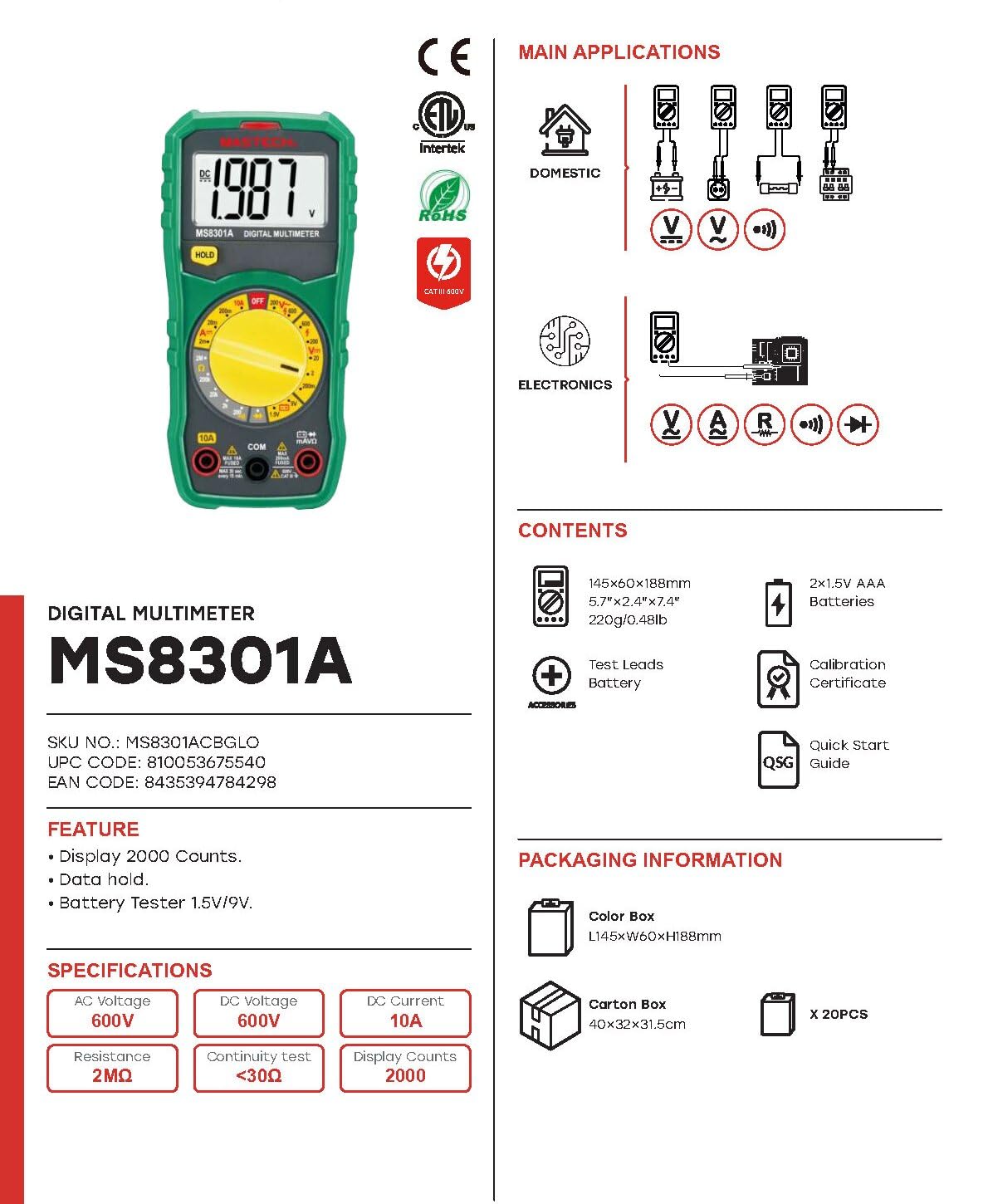
Image: This image provides an overview of the MS8301A Digital Multimeter, highlighting its main applications (domestic and electronics) and listing the typical package contents, including the meter, test leads, batteries, and documentation.
5. Setup
5.1 Battery Installation
- Ensure the multimeter is turned off.
- Locate the battery compartment cover on the back of the meter.
- Use a screwdriver to remove the screw securing the battery cover.
- Insert two 1.5V AAA batteries, observing the correct polarity (+ and -).
- Replace the battery cover and secure it with the screw.
5.2 Connecting Test Leads
Insert the black test lead into the 'COM' (common) jack. Insert the red test lead into the appropriate input jack for your measurement:
- For voltage, resistance, diode, and continuity measurements, insert the red lead into the 'VΩmA' jack.
- For current measurements up to 10A, insert the red lead into the '10A' jack.
6. Operating Instructions
6.1 Power On/Off
Turn the rotary switch from the 'OFF' position to the desired measurement function to power on the meter. To power off, turn the rotary switch back to 'OFF'.
6.2 DC Voltage Measurement (V–)
- Set the rotary switch to the desired DC Voltage range (e.g., 200mV, 2V, 20V, 200V, 600V).
- Connect the black test lead to the 'COM' jack and the red test lead to the 'VΩmA' jack.
- Connect the test leads across the component or circuit to be measured, observing polarity.
- Read the voltage value on the display.
6.3 AC Voltage Measurement (V∼)
- Set the rotary switch to the desired AC Voltage range (e.g., 200V, 600V).
- Connect the black test lead to the 'COM' jack and the red test lead to the 'VΩmA' jack.
- Connect the test leads across the AC voltage source.
- Read the voltage value on the display.
6.4 DC Current Measurement (A–)
- Set the rotary switch to the desired DC Current range (e.g., 2mA, 20mA, 200mA, 10A).
- For measurements up to 200mA, connect the red test lead to the 'VΩmA' jack. For measurements up to 10A, connect the red test lead to the '10A' jack. The black lead always connects to 'COM'.
- Open the circuit where current is to be measured and connect the meter in series with the load.
- Read the current value on the display.
6.5 Resistance Measurement (Ω)
- Set the rotary switch to the desired Resistance range (e.g., 200Ω, 2kΩ, 20kΩ, 200kΩ, 2MΩ).
- Connect the black test lead to the 'COM' jack and the red test lead to the 'VΩmA' jack.
- Ensure the circuit is de-energized. Connect the test leads across the resistor or component.
- Read the resistance value on the display.
6.6 Diode Test
- Set the rotary switch to the Diode symbol position.
- Connect the black test lead to the 'COM' jack and the red test lead to the 'VΩmA' jack.
- Connect the red test lead to the anode and the black test lead to the cathode of the diode. The display will show the forward voltage drop.
- Reverse the leads. The display should show 'OL' (Open Loop) for a good diode.
6.7 Continuity Test
- Set the rotary switch to the Continuity symbol position.
- Connect the black test lead to the 'COM' jack and the red test lead to the 'VΩmA' jack.
- Connect the test leads across the circuit or component.
- If the resistance is below approximately 30Ω, the built-in buzzer will sound, indicating continuity.
6.8 Battery Test (1.5V/9V)
- Set the rotary switch to the '1.5V' or '9V' battery test position.
- Connect the black test lead to the 'COM' jack and the red test lead to the 'VΩmA' jack.
- Connect the test leads to the positive and negative terminals of the battery, observing polarity.
- The display will show the battery voltage. A reading significantly below the nominal voltage indicates a weak or discharged battery.
6.9 Data Hold
Press the 'HOLD' button to freeze the current reading on the display. Press it again to release the hold function and resume live readings.
7. Maintenance
7.1 Battery Replacement
When the low battery indicator appears on the display, replace the batteries as described in Section 5.1. Always use two fresh 1.5V AAA batteries.
7.2 Cleaning
Wipe the meter casing with a damp cloth and a mild detergent. Do not use abrasives or solvents. Ensure the meter is completely dry before use.
8. Troubleshooting
- No Display: Check battery installation and ensure batteries are fresh. Ensure the rotary switch is not in the 'OFF' position.
- 'OL' or '1' on Display: This usually indicates an over-range condition or an open circuit. Check if the measurement range is too low or if the test leads are properly connected.
- Incorrect Readings: Verify the correct function and range are selected. Check test lead connections and battery condition. Ensure the circuit under test is de-energized for resistance/continuity tests.
9. Specifications
Below are the general and electrical specifications for the GuliTech MS8301A Digital Multimeter:
General Specifications:
- Display: 2000 Counts
- Power Supply: 2 x 1.5V AAA Batteries
- Dimensions (L x W x H): 150mm x 74mm x 48mm (5.9" x 2.9" x 1.7")
- Weight: Approximately 220g (0.48lb)
- Safety Rating: CAT II 600V, CAT III 300V
- Operating Temperature: 0℃ to 50℃
- Storage Temperature: -10℃ to 50℃
- Compliance: CE, RoHS
Electrical Specifications:
| Function | Range | Resolution |
|---|---|---|
| DC Voltage | 200mV / 2V / 20V / 200V / 600V | 100µV / 1mV / 10mV / 100mV / 1V |
| AC Voltage | 200V / 600V | 100mV / 1V |
| DC Current | 2mA / 20mA / 200mA / 10A | 1µA / 10µA / 100µA / 10mA |
| Resistance | 200Ω / 2kΩ / 20kΩ / 200kΩ / 2MΩ | 0.1Ω / 1Ω / 10Ω / 100Ω / 1kΩ |
| Continuity Test | Buzzer sounds at <30Ω | N/A |
| Diode Test | Forward voltage drop | N/A |
| Battery Test | 1.5V / 9V | N/A |

Image: This table provides detailed specifications for various digital multimeter models, including the MS8301A, outlining display counts, safety ratings, auto ranging, True RMS, and measurement ranges for DC Voltage, AC Voltage, DC Current, Resistance, Capacitance, Frequency, Duty Cycle, Temperature, Battery Test, Diode, Continuity, Display Backlight, Work Light, Data Hold, NCV, Inductance, HFE Transistor, Dual Display, MAX/MIN, Relative Measurement, Peak Measurement, DWELL Test, and TACH Test.
10. Warranty and Support
GuliTech products are designed for reliability and performance. This product comes with a standard manufacturer's warranty. For specific warranty details, please refer to the documentation included with your purchase or contact GuliTech customer support.
For technical support, troubleshooting assistance, or warranty claims, please contact your retailer or visit the official GuliTech website for contact information.