1. Introduction
This manual provides detailed instructions for the installation, operation, and maintenance of your Stinger Audio MT-1000.1M 1-Channel Monoblock Marine Audio Subwoofer Amplifier. Please read this manual thoroughly before attempting installation or operation to ensure proper use and to prevent damage to the unit or your audio system. Keep this manual for future reference.
2. Product Overview
The Stinger Audio MT-1000.1M is a high-efficiency Class-D monoblock amplifier designed for marine environments. It delivers 1000 Watts RMS of power, optimized for subwoofer applications. Its robust, water-resistant design ensures reliable performance in challenging conditions.
Key Features:
- Digital Class-D Monoblock Amplifier: High efficiency and compact form factor.
- Compact and Sturdy Design: Built for lasting reliability.
- Robust Unregulated Power Supplies: Designed for superior performance and efficiency.
- Advanced HEXFET Power MOSFET: Features reduced on-resistance, faster switching speeds, and enhanced reliability.
- Direct Insert Power and Speaker Terminals: Decreased resistance for higher power transfer and efficiency.
- Water-Resistant Design: Protects the amplifier against weather elements for uninterrupted performance.
- Bass Boost Q: Adjustable bass boost from 0dB to 12dB at a selected frequency.
- Remote Bass Knob Included: Flush-mount design for effortless bass level adjustment.

3. Safety Information
Always observe the following safety precautions:
- Disconnect the vehicle's negative battery terminal before any installation.
- Ensure proper grounding to the vehicle chassis.
- Use appropriate gauge wiring for power, ground, and speaker connections.
- Install the amplifier in a well-ventilated area, away from direct heat sources.
- Avoid mounting the amplifier in locations where it may be submerged in water, despite its water-resistant rating.
- Consult a professional installer if you are unsure about any part of the installation process.
4. What's in the Box
Verify that all items are present before beginning installation:
- 1000 Watt Monoblock Amplifier (MT-1000.1M)
- Remote Level Control (Bass Knob)
- Mounting Hardware
- Instruction Manual
5. Component Identification
Familiarize yourself with the amplifier's controls and connections.

5.1 Control Panel (Input Side)

- POWER/PRT/CLIP Indicators: LEDs indicating power status, protection mode, and signal clipping.
- REMOTE Port: RJ11 connection for the included remote bass level control.
- INPUT (RCA): Audio input from your head unit or source.
- BRIDGE IN/OUT (RCA): For linking multiple amplifiers.
- GAIN Control: Adjusts the input sensitivity to match the output of your source unit.
- LPF (Low-Pass Filter) Control: Adjusts the upper frequency limit for the subwoofer. Range: 40Hz - 180Hz.
- SUBSONIC Filter: Removes ultra-low frequencies below the audible range to protect the subwoofer. Range: OFF - 50Hz.
- FREQ (Bass Boost Frequency) Control: Selects the center frequency for the bass boost. Range: 30Hz - 80Hz.
- BOOST (Bass Boost Level) Control: Adjusts the level of bass boost. Range: 0dB - 12dB.
5.2 Terminal Panel (Output Side)

- GND (Ground) Terminal: Connects to the vehicle's chassis ground.
- REM (Remote) Terminal: Connects to the remote turn-on lead from your source unit.
- +12V (Power) Terminal: Connects to the positive terminal of the vehicle's battery via an inline fuse.
- MONO OUTPUT (Speaker Terminals): Connects to your subwoofer(s). Minimum impedance 1 Ohm.
6. Installation
Proper installation is crucial for optimal performance and safety. Ensure all connections are secure and correctly polarized.
6.1 Mounting Location
Choose a mounting location that is secure, provides adequate ventilation, and is protected from excessive moisture. While the amplifier is water-resistant, direct exposure to heavy water spray or submersion should be avoided.

6.2 Wiring Connections
- Power (B+): Connect a 4-gauge power cable from the +12V terminal of the amplifier directly to the positive terminal of the vehicle's battery. Install an appropriate inline fuse (100A recommended) within 18 inches of the battery.
- Ground (GND): Connect a 4-gauge ground cable from the GND terminal of the amplifier to a clean, bare metal point on the vehicle's chassis. Ensure a solid, low-resistance connection.
- Remote (REM): Connect a 18-gauge remote turn-on wire from the REM terminal of the amplifier to the remote output of your head unit.
- RCA Input: Connect RCA cables from the subwoofer output of your head unit to the INPUT RCA jacks on the amplifier.
- Speaker Output: Connect your subwoofer(s) to the MONO OUTPUT terminals. Ensure the total impedance is not below 1 Ohm. Observe correct polarity (+ to + and - to -).
- Remote Bass Knob: Connect the remote bass knob to the REMOTE port on the amplifier using the provided cable.
7. Operation
After installation, follow these steps to configure and operate your amplifier.
7.1 Initial Setup and Gain Adjustment
- Turn the GAIN control on the amplifier to its minimum (counter-clockwise) position.
- Set your head unit's volume to about 75% of its maximum level.
- Play a dynamic piece of music with strong bass content.
- Slowly increase the GAIN control on the amplifier until you hear distortion, then back it off slightly until the sound is clear. The CLIP indicator should not illuminate continuously.
7.2 Crossover and Filter Settings
- LPF (Low-Pass Filter): Adjust the LPF control to set the upper frequency limit for your subwoofer. A common starting point is 80Hz-100Hz, but this may vary depending on your subwoofer and other speakers in your system.
- SUBSONIC Filter: Set the SUBSONIC filter to protect your subwoofer from playing frequencies below its resonant frequency. A common setting is 25Hz-30Hz, or slightly below your subwoofer's tuning frequency if it's in a ported enclosure. If you have a sealed enclosure, you may set it to OFF or a very low frequency.
7.3 Bass Boost
- FREQ (Bass Boost Frequency): Select the frequency at which you want the bass boost to be centered. This is typically between 30Hz and 80Hz, depending on the desired effect.
- BOOST (Bass Boost Level): Adjust the level of boost from 0dB to 12dB. Use this sparingly to avoid distortion and potential damage to your subwoofer.
7.4 Remote Bass Knob
The remote bass knob allows for convenient adjustment of the subwoofer output level from your listening position. It acts as a master volume for the subwoofer channel, allowing you to increase or decrease the bass intensity without affecting other amplifier settings.
8. Maintenance
Regular maintenance helps ensure the longevity and performance of your amplifier.
- Cleaning: Periodically wipe the amplifier's exterior with a soft, dry cloth. Avoid using harsh chemicals or abrasive cleaners.
- Connection Check: Annually inspect all power, ground, remote, and speaker connections for corrosion or looseness. Tighten as necessary.
- Ventilation: Ensure that the amplifier's cooling fins are free from obstructions to allow for proper heat dissipation.
9. Troubleshooting
If you experience issues with your amplifier, refer to the following common problems and solutions.
| Problem | Possible Cause | Solution |
|---|---|---|
| No Power / Power LED Off | Blown fuse, loose power/ground/remote wire, no remote signal. | Check inline fuse, verify all power connections, ensure head unit remote output is active. |
| Protection LED On | Speaker short circuit, impedance too low, overheating, DC offset. | Check speaker wiring for shorts, verify speaker impedance, ensure adequate ventilation, disconnect speakers and test. |
| No Audio Output | No input signal, incorrect gain setting, speaker wires disconnected. | Check RCA connections, adjust gain, verify speaker connections. |
| Distorted Sound | Gain set too high, improper crossover settings, poor ground connection. | Reduce gain, adjust LPF/Subsonic filters, check ground wire for secure connection. |
10. Specifications
Detailed technical specifications for the Stinger Audio MT-1000.1M amplifier.
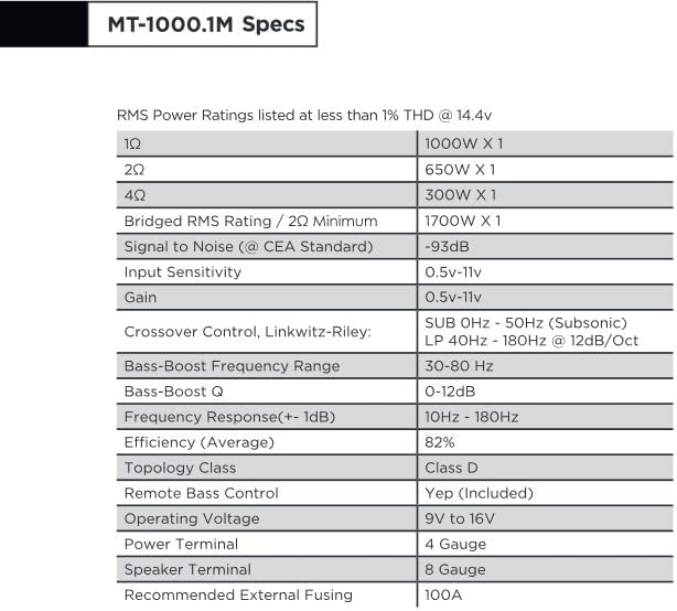
| Feature | Specification |
|---|---|
| RMS Power (1Ω) | 1000W x 1 |
| RMS Power (2Ω) | 650W x 1 |
| RMS Power (4Ω) | 300W x 1 |
| Bridged RMS Rating (2Ω Minimum) | 1700W x 1 |
| Signal to Noise (CEA Standard) | -93dB |
| Input Sensitivity | 0.5V - 11V |
| Gain | 0.5V - 11V |
| Crossover Control (Linkwitz-Riley) | SUB 0Hz - 50Hz (Subsonic), LP 40Hz - 180Hz @ 12dB/Oct |
| Bass-Boost Frequency Range | 30Hz - 80Hz |
| Bass-Boost Q | 0 - 12dB |
| Frequency Response (+/- 1dB) | 10Hz - 180Hz |
| Efficiency (Average) | 82% |
| Topology Class | Class D |
| Remote Bass Control | Yes (Included) |
| Operating Voltage | 9V to 16V |
| Power Terminal | 4 Gauge |
| Speaker Terminal | 8 Gauge |
| Recommended External Fusing | 100A |
| Item Weight | 6.14 pounds |
| Package Dimensions | 14.5 x 7.8 x 3.2 inches |
| Date First Available | March 13, 2024 |
| Manufacturer | STINGER |
11. Warranty and Support
11.1 Warranty Information
The Stinger Audio MT-1000.1M amplifier comes with a 1 Year Warranty from the date of purchase. Please retain your proof of purchase for warranty claims. The warranty covers manufacturing defects and workmanship under normal use. It does not cover damage caused by improper installation, accident, misuse, abuse, neglect, or unauthorized modification.
11.2 Customer Support
For technical assistance, troubleshooting, or warranty inquiries, please contact Stinger Audio customer support. You can find more information and contact details by visiting the official STINGER brand store:


