
1. Introduction
This manual provides essential information for the safe and effective use of the Teyleten Robot LM2596S LM2596 Buck Converter module. This device is a DC-DC step-down voltage regulator designed to convert a higher input voltage to a lower, adjustable output voltage. Please read these instructions carefully before installation and operation to ensure proper functionality and to prevent damage to the module or connected components.
2. Product Overview
The LM2596S module is a highly efficient step-down (buck) switching regulator capable of driving a 3A load with excellent line and load regulation. It features a built-in fixed frequency oscillator (65 kHz) and a wide input voltage range, making it suitable for various electronic projects and power supply applications.
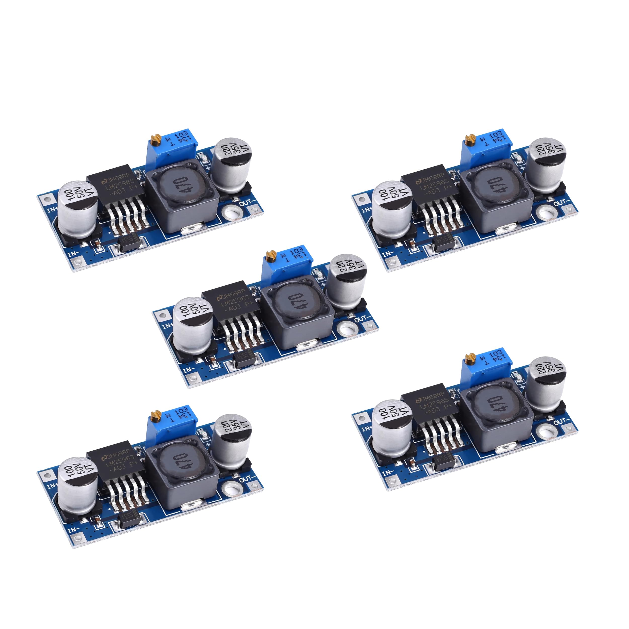
Figure 2.1: Top view of the LM2596S Buck Converter module. This image displays the main components including the LM2596S integrated circuit, the large inductor, electrolytic capacitors, and the blue multi-turn potentiometer used for voltage adjustment.

Figure 2.2: Angled view of the LM2596S Buck Converter module. This perspective clearly shows the input terminals labeled 'IN+' and 'IN-' on one side, and the output terminals 'OUT+' and 'OUT-' on the opposite side, facilitating connection identification.
3. Specifications
| Feature | Specification |
|---|---|
| Input Voltage Range | DC 3.2V to 40V |
| Output Voltage Range | DC 1.25V to 35V (Adjustable) |
| Output Current | 3A (Maximum) |
| Conversion Efficiency | Up to 92% (Maximum) |
| Switching Frequency | 65 KHz |
| Output Ripple | <30mV |
| Operating Temperature | -45℃ to +85℃ |
| Module Type | Non-isolated step-down module (BUCK) |
Note: The input voltage must be at least 1.5V higher than the desired output voltage for proper regulation. This module is a step-down converter and cannot boost voltage.
4. Setup
- Identify Terminals: Locate the input terminals (IN+ for positive, IN- for negative) and output terminals (OUT+ for positive, OUT- for negative) on the module.
- Connect Input Power: Connect your DC power source to the IN+ and IN- terminals. Ensure correct polarity. The input voltage must be within the specified range of 3.2V to 40V DC.
- Connect Load: Connect your load device to the OUT+ and OUT- terminals. Ensure correct polarity.
- Adjust Output Voltage:
- Before connecting a sensitive load, it is highly recommended to adjust the output voltage first.
- Connect a voltmeter to the OUT+ and OUT- terminals.
- Apply input power.
- Using a small screwdriver, carefully turn the multi-turn potentiometer (the blue component with a screw) clockwise to increase the output voltage or counter-clockwise to decrease it.
- Adjust until the desired output voltage is displayed on the voltmeter.
- Verify Operation: Once the output voltage is set, you can connect your load and verify its proper operation.
5. Operating Instructions
- Voltage Adjustment: The output voltage is continuously adjustable within its specified range (1.25V to 35V). Always adjust the voltage with a voltmeter connected to the output before connecting your final load.
- Current Limit: The module can supply up to 3A of output current. Do not exceed this limit to prevent damage to the module. For continuous operation at higher currents, consider adding a heatsink to the LM2596S chip.
- Input Voltage Requirement: Always ensure the input voltage is at least 1.5V higher than your desired output voltage. For example, if you need 5V output, the input must be at least 6.5V.
- Polarity: Double-check all connections for correct polarity (IN+, IN-, OUT+, OUT-) before applying power. Incorrect polarity can damage the module and connected devices.
6. Maintenance
- Cleaning: Keep the module clean and free from dust and debris. Use a soft, dry brush or compressed air for cleaning. Do not use liquids.
- Environmental Conditions: Operate the module within its specified operating temperature range (-45℃ to +85℃). Avoid exposure to excessive moisture, extreme temperatures, or corrosive environments.
- Inspection: Periodically inspect the module for any signs of physical damage, loose connections, or discoloration of components, which may indicate overheating.
7. Troubleshooting
- No Output Voltage:
- Check if input power is applied and within the specified range.
- Verify input and output wiring for correct polarity and secure connections.
- Ensure the input voltage is sufficiently higher than the desired output voltage (at least 1.5V difference).
- Turn the potentiometer multiple turns in both directions to ensure it's not at an extreme setting.
- Output Voltage is Unstable or Incorrect:
- Re-adjust the potentiometer slowly while monitoring with a voltmeter.
- Check if the load current exceeds the maximum 3A rating. Reduce the load if necessary.
- Ensure the input power supply is stable and can provide sufficient current.
- Module Overheating:
- Reduce the output current or the difference between input and output voltage.
- Consider adding a heatsink to the LM2596S chip, especially for continuous operation at higher currents or larger voltage drops.
8. Safety Information
- Always disconnect power before making any connections or adjustments to the module.
- Ensure proper insulation to prevent short circuits.
- Do not touch the module components when power is applied, as some parts may become hot.
- This module is intended for use by individuals with appropriate knowledge of electronics and electrical safety.
- Do not exceed the maximum input voltage or output current ratings.
9. Warranty and Support
For warranty information, technical support, or inquiries regarding the Teyleten Robot LM2596S Buck Converter module, please contact the manufacturer directly. You can find more information and contact details by visiting the official Teyleten Robot Store.