
1. Product Overview
The Greluma 3-Way Bilge Pump Control Panel provides comprehensive control over your bilge pump system. It features three operational modes: Manual, Off, and Automatic, allowing for flexible management of water removal. Equipped with LED indicators for clear status display and an integrated 5A circuit breaker for circuit protection, this panel is designed for reliable performance in DC 12V marine environments.
2. Product Features
- 3-Way Rocker Switch: Offers Manual, Off, and Automatic control modes for the bilge pump.
- Durable Construction: Manufactured from high-quality ABS material, ensuring durability, scratch resistance, corrosion resistance, high strength, good toughness, and anti-aging properties for a long service life.
- LED Indicators: Provides visual feedback on the operating status. A red light indicates manual operation, and a green light indicates automatic operation, enhancing visibility, especially in low-light conditions.
- Integrated 5A Circuit Breaker: Ensures circuit safety by protecting against short circuits. The circuit can be reset by simply pressing the breaker button.
- High Reliability: Designed to protect your bilge pump from the effects of intermittent high current, preventing motor burnout and ensuring consistent performance.
- Wide Application: Suitable for various 12V DC applications including marine boats, yachts, RVs, and other vehicles requiring bilge pump control.
3. Package Contents
Please verify that all components are present upon unpacking:
- 1 x Greluma 3-Way Bilge Pump Control Panel
- 1 x 5A Fuse (integrated)
- 4 x Mounting Screws
4. Specifications
| Feature | Specification |
|---|---|
| Model Number | ZL804LUM |
| Operating Voltage | DC 12 Volts |
| Current Rating | 5 Amperes (integrated circuit breaker) |
| Switch Type | Rocker, 3-Way (Manual-Off-Auto) |
| Control Method | Tactile |
| Material | ABS |
| Dimensions (L x W x H) | 11 x 9 x 7.4 cm (4.33 x 3.54 x 2.91 inches) |
| Weight | 110 grams |
| Mounting Type | Surface/Panel Mounted |
| Connector Type | Screw Terminal |
| International Protection Rating | IP00 |
| Compliance | CE |

Figure 1: Product dimensions and replaceable fuse location. The panel measures approximately 90mm (3.54 inches) wide by 50mm (1.97 inches) high on the front face. The rear housing is approximately 74mm (2.91 inches) wide by 35mm (1.38 inches) high, with a depth of 40mm (1.57 inches) from the mounting surface. A 5A fuse is integrated and accessible for replacement.
5. Safety Information
WARNING: This device is designed for use only on 12 Volt DC systems. Connecting the pump, float switch, and 3-way switch improperly can lead to malfunction of the float switch, cause the pump to run in reverse, or damage the pump motor. Incorrect wiring will void the product warranty and may create hazardous conditions, including electrical fires or system failures. Always ensure proper polarity and secure connections.
- Always disconnect power before installation or maintenance.
- Ensure all wiring connections are secure and properly insulated to prevent short circuits.
- Verify that the bilge pump and float switch are compatible with a 12V DC system and the 5A current rating.
- Do not exceed the maximum current rating of 5A. The integrated circuit breaker will trip if overloaded.
- Consult a qualified marine electrician if you are unsure about any part of the installation process.
6. Setup and Installation
Follow these steps for proper installation of the bilge pump control panel. Refer to the wiring diagrams for visual guidance.
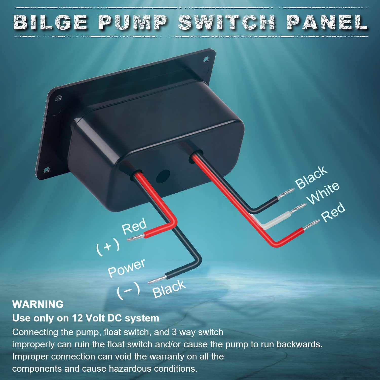
Figure 2: Overview of the wiring connections for the bilge pump control panel. The panel has three wires: Red (+) Power, Black (-) Ground, and a Red wire for the pump. The float switch typically has White, Red, and Black wires.

Figure 3: Detailed wiring instructions for connecting the bilge pump control panel to a float switch and pump.
- Step 1: Connect the white wire from the bilge pump control panel to the float switch. This connection can be made to either side of the float switch's signal input.
- Step 2: Connect the black wire from the bilge pump control panel to the negative side of the pump.
- Step 3: Connect the red wire from the bilge pump control panel to the positive side of the pump. This is typically the red or brown/white wire from the pump, and also connect it to the other side of the float switch's signal output.
- Step 4: Connect the black wire from the bilge pump control panel to the negative side of the battery or a common ground point (12V DC system only).
- Step 5: Connect the red wire from the bilge pump control panel to the positive bus bar, terminal, or main power source (12V DC system only).
Note: Before use, ensure that the two wires intended for the float switch and pump exit from the correct holes in the panel housing to maintain proper sealing and organization.
7. Operating Instructions
The Greluma Bilge Pump Control Panel features a 3-way rocker switch for easy operation and LED indicators to show the current status.

Figure 4: Visual representation of the LED indicators for Manual and Automatic operating modes.
- Manual Mode:
When the rocker switch is moved to the "MANUAL" position, the bilge pump will operate continuously. The RED LED light will illuminate, indicating manual operation. Move the switch to "OFF" to stop the pump.
- Off Mode:
When the rocker switch is in the center "OFF" position, the bilge pump will not operate, regardless of the water level. Both LED indicators will be off.
- Automatic Mode:
When the rocker switch is moved to the "AUTO" position, the bilge pump will be controlled by the connected float switch. The GREEN LED light will remain illuminated constantly, indicating that the system is in automatic mode. The RED LED light will also illuminate each time the pump is activated by the float switch.
Final Check:
- When the switch is in "MANUAL" position, the RED light should be on.
- When in "AUTO" position, the GREEN light is on all the time, and the RED light comes on each time the pump is activated by the float switch.
- If both lights are not on when expected, or if the pump operates incorrectly, review the wiring and troubleshoot as necessary.
8. Maintenance
- Regular Inspection: Periodically check all wiring connections for corrosion, fraying, or looseness. Ensure the panel is securely mounted.
- Cleaning: Clean the panel surface with a damp cloth. Avoid using abrasive cleaners or solvents that could damage the ABS material or markings.
- Fuse Replacement: The panel includes an integrated 5A circuit breaker. If the breaker trips frequently, investigate the cause of the overload. If a fuse needs replacement (for models with a separate fuse holder), ensure to use a 5A fuse of the correct type.
- Float Switch Check: Regularly test the float switch operation to ensure it activates the pump correctly in automatic mode.
9. Troubleshooting
| Problem | Possible Cause | Solution |
|---|---|---|
| Pump does not operate in MANUAL mode. | No power to the panel; faulty wiring; tripped circuit breaker; faulty pump. | Check battery connections and power supply. Verify all wiring connections. Reset the 5A circuit breaker. Test the pump directly if possible. |
| Pump does not operate in AUTO mode when water level rises. | Faulty float switch; incorrect float switch wiring; no power to the panel. | Check float switch operation (manually lift it). Verify float switch wiring according to diagram. Ensure power supply to the panel. |
| Pump runs continuously in AUTO mode. | Stuck float switch; incorrect float switch wiring. | Inspect float switch for obstructions. Verify float switch wiring. |
| LED indicators are not working. | No power to the panel; faulty wiring; LED malfunction. | Check power supply and wiring. If power is present and wiring is correct, the LEDs may be faulty. |
| Circuit breaker trips frequently. | Overload on the circuit; short circuit in wiring or pump; faulty pump. | Reduce load if possible. Inspect all wiring for shorts. Check the bilge pump for signs of damage or excessive current draw. |
10. Warranty and Support
Specific warranty information for this product is not provided in the available documentation. For any support inquiries, technical assistance, or warranty claims, please contact your retailer or the manufacturer, Greluma, directly through their official channels. Please have your product model number (ZL804LUM) and purchase details ready when contacting support.