1. Introduction
This manual provides essential information for the safe and efficient operation of your EPEVER Tracer6415AN MPPT Solar Charge Controller. The Tracer-AN series is designed for advanced solar power systems, offering high efficiency and comprehensive protection features. This 60A model supports various battery voltages and can manage up to 3000W of solar panel input for 48V systems.
Key Features:
- Advanced Maximum Power Point Tracking (MPPT) technology with tracking efficiency ≥99.5%.
- High conversion efficiency >98.6%.
- Automatic detection for 12V/24V/36V/48V battery systems.
- Support for Sealed, Gel, AGM, Flooded, and Lithium battery types.
- Real-time energy statistics and LCD display for operational data.
- Multiple load control modes.
- Comprehensive electronic protection against overcharge, over-discharge, overload, short circuit, reverse polarity, and overheating.
- Negative ground design.
2. Safety Instructions
Please read all instructions carefully before installation and operation. Failure to follow these instructions may result in serious injury, damage to the controller, or damage to other components of the system.
- Ensure all wiring is correctly polarized and securely connected.
- Do not attempt to repair or modify the controller. Refer to qualified service personnel.
- Install the controller in a well-ventilated area, away from flammable materials.
- Disconnect all power sources (solar panel and battery) before installing or servicing the controller.
- Use appropriate circuit breakers or fuses for all connections.
- Wear eye protection when working with batteries.
- Ensure the battery bank voltage is within the controller's operating range.
3. Product Components and Features
Familiarize yourself with the various parts and connections of the Tracer6415AN controller.

Figure 3.1: Front and Side View of the Tracer6415AN Controller with Labeled Components.
This image displays the EPEVER Tracer6415AN MPPT Solar Charge Controller, highlighting its key features and connection points. The left panel shows the front view with the LCD display and control buttons. The right panel provides a detailed perspective of the connection terminals and ports, including PV terminals, battery terminals, load control relay, RS485 port, RTS port, and grounding terminal. The image also points out the fuse, generator relay ON/OFF, and PV reverse polarity alarm indicator.
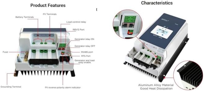
Figure 3.2: Product Features and Characteristics Overview.
This image provides a visual breakdown of the Tracer6415AN's external features and internal characteristics. The left side details the various terminals and ports: Battery Terminals, PV Terminals, Load control relay, RBVS Port, Generator relay ON/OFF, RS485 port, RTS Port, Generator and load relay enable, Fuse, Grounding Terminal, and PV reverse polarity alarm indicator. The right side illustrates the overall characteristics, emphasizing the aluminum alloy material for good heat dissipation and showing the LCD display interface.
Component Identification:
- Charging LED indicator
- SELECT button
- Fuse
- Grounding Terminal
- Fault LED indicator
- LCD
- ENTER button
- RBVS Port
- Utility/Generator relay ON
- RS485 port (5V/DC200mA)
- RTS Port
- Generator and load relay enable
- PV reverse polarity alarm indicator
- Load control relay
- Utility/Generator relay OFF
- PV Terminals
- Battery Terminals
4. Installation and Wiring
Proper installation is crucial for the safe and efficient operation of your solar charge controller. Follow these steps carefully.
4.1 Mounting the Controller
- Choose a suitable mounting location that is dry, well-ventilated, and protected from direct sunlight and moisture.
- Ensure there is sufficient clearance around the controller for proper heat dissipation.
- Mount the controller vertically on a non-flammable surface using appropriate fasteners.
4.2 Wiring Diagram
The following diagram illustrates a typical wiring setup for the Tracer6415AN controller in a solar power system.
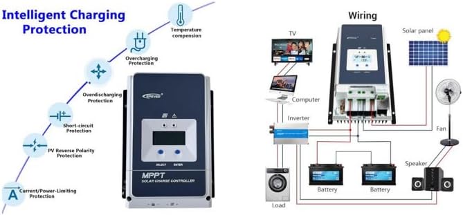
Figure 4.1: Typical Wiring Diagram for a Solar System with Tracer6415AN.
This image presents a comprehensive wiring diagram for integrating the EPEVER Tracer6415AN MPPT Solar Charge Controller into a solar power system. It shows connections from the solar panel to the controller, from the controller to the battery bank (two batteries shown), and from the battery bank to an inverter, which then powers various AC loads like a TV, computer, and washing machine. Additionally, DC loads such as a fan and speaker are shown connected directly to the controller's load terminals. The left side of the image also illustrates the controller's intelligent charging protection features, including temperature compensation, overcharging protection, over-discharging protection, short-circuit protection, PV reverse polarity protection, and current/power-limiting protection.
4.3 Connection Sequence
Follow this sequence to connect the components to the controller:
- Connect the Battery: Connect the battery to the controller's battery terminals. Ensure correct polarity. The controller will automatically detect the battery voltage (12V/24V/36V/48V).
- Connect the Solar Panel: Connect the solar panel to the controller's PV terminals. Ensure correct polarity.
- Connect the Load (Optional): Connect DC loads to the controller's load terminals. Ensure correct polarity.
- Grounding: Connect the grounding terminal to an earth ground.
Warning: Always connect the battery first and disconnect the battery last. Incorrect connection order may damage the controller.
5. Operating Instructions
The Tracer6415AN features an LCD display and control buttons for monitoring and configuration.
5.1 LCD Display
The LCD displays real-time operating data, including battery voltage, PV voltage, charging current, load current, and system status. Use the "SELECT" and "ENTER" buttons to navigate through the display menus and adjust settings.
5.2 Battery Type Selection
The controller supports various battery types. You can select the appropriate battery type (Sealed, Gel, AGM, Flooded, Lithium, or User-defined) through the controller's menu. For 36V systems, the battery type needs to be adjusted manually.
5.3 Load Control Modes
The controller offers multiple load control modes, allowing you to manage when your DC loads receive power. Refer to the detailed manual for specific programming instructions for each mode.
6. Protection Features
The Tracer6415AN is equipped with comprehensive electronic protection functions to ensure system safety and longevity.
- PV Over Current Protection: Prevents damage from excessive current from the solar array.
- PV Short Circuit Protection: Protects against short circuits in the solar array.
- PV Reverse Polarity Protection: Prevents damage if solar panel polarity is reversed.
- Battery Overcharge Protection: Stops charging when the battery reaches its full charge voltage.
- Battery Over-discharge Protection: Disconnects the load when the battery voltage drops too low, preventing deep discharge.
- Battery Reverse Polarity Protection: Protects against incorrect battery connection.
- Load Overload Protection: Disconnects the load if current exceeds the rated value.
- Load Short Circuit Protection: Protects against short circuits in the load circuit.
- Controller Overheating Protection: Reduces charging current or disconnects if the controller temperature becomes too high.
7. Specifications
| Parameter | Value |
|---|---|
| System Nominal Voltage | 12V/24V/36V/48V Auto Work |
| Rated Charge Current | 60A |
| Max. PV Input Voltage | 150V |
| MPPT Tracking Efficiency | ≥99.5% |
| Conversion Efficiency | >98.6% |
| Max. PV Input Power (12V) | 750W |
| Max. PV Input Power (24V) | 1500W |
| Max. PV Input Power (36V) | 2250W |
| Max. PV Input Power (48V) | 3000W |
| Battery Types Supported | Sealed, Gel, AGM, Flooded, Lithium, User-defined |
| Grounding | Negative Ground |
8. Maintenance
Regular maintenance ensures optimal performance and extends the lifespan of your charge controller.
- Check Connections: Periodically inspect all wiring connections for tightness and corrosion.
- Clean the Controller: Keep the controller clean and free from dust and debris. Ensure ventilation openings are not blocked.
- Inspect for Damage: Check for any physical damage to the casing, cables, or terminals.
- Monitor Performance: Regularly check the LCD display for normal operation and any error codes.
9. Troubleshooting
This section provides solutions to common issues you might encounter.
| Problem | Possible Cause | Solution |
|---|---|---|
| No display on LCD | Battery not connected or low voltage; reverse polarity. | Check battery connections and voltage. Ensure correct polarity. |
| No charging current | PV panels not connected; low sunlight; PV reverse polarity; PV short circuit. | Check PV connections and polarity. Verify sunlight conditions. Inspect PV wiring for shorts. |
| Load not working | Load disconnected; overload; short circuit; battery low voltage. | Check load connections. Reduce load. Inspect load wiring for shorts. Charge battery. |
| Controller overheating | Poor ventilation; excessive ambient temperature; prolonged high current. | Ensure adequate ventilation. Relocate controller if ambient temperature is too high. Reduce load or PV input if possible. |
10. Product Videos
Watch these official product videos for additional guidance and visual demonstrations.
10.1 EPEVER Tracer-AN Series Overview (1:08)
This video provides a concise overview of the EPEVER Tracer-AN series MPPT solar charge controllers, highlighting their main features, design, and applications. It offers a quick visual introduction to the product line.
10.2 EPEVER Tracer-AN Series Detailed Explanation (3:40)
This video offers a more detailed explanation of the EPEVER Tracer-AN series, delving deeper into its functionalities, advanced MPPT technology, and various protection mechanisms. It may include demonstrations of the LCD interface and settings.
11. Warranty and Support
EPEVER products are designed for reliability and performance. For warranty information, technical support, or service inquiries, please refer to the official EPEVER website or contact your authorized dealer.
Keep your purchase receipt as proof of purchase for warranty claims.


