1. Introduction
This user manual provides comprehensive instructions for the installation, configuration, and operation of your DieseRC 1-Channel WiFi Smart Relay Module (Model EW748). Please read this manual carefully before using the device to ensure proper functionality and safety. Keep this manual for future reference.
2. Product Overview
The DieseRC 1-Channel WiFi Smart Relay Module is a wireless intelligent switch designed to integrate various electrical devices into your smart home system. It offers remote control capabilities via the eWelink app, voice control compatibility with Amazon Alexa and Google Home, and flexible operating modes (inching/self-locking). The module features a passive output (dry contact) and supports a wide range of DC input voltages.

Image 2.1: Top-down view of the DieseRC 1-Channel WiFi Smart Relay Module, highlighting its compact design and components.

Image 2.2: Illustration of multiple DieseRC smart relay modules being controlled via the eWelink application, demonstrating multi-device management.
3. Specifications
| Feature | Detail |
|---|---|
| Model Number | EW748 |
| Input Voltage | DC 5V or DC 7V-48V |
| Output Type | Passive Output (Dry Contact) |
| Contact Rating | 10A (Max) |
| Power Consumption | 360 Watts (Max) |
| Connectivity | 2.4 GHz WiFi |
| Operating Modes | Inching Mode, Self-locking Mode |
| App Compatibility | eWelink (Android & iOS) |
| Voice Control | Amazon Alexa, Google Home |
| Dimensions (L x W x H) | 55 x 29 x 17 mm (2.2 x 1.1 x 0.7 inches) |
| Certification | CE |
4. Setup
4.1 Package Contents
- 1 x DieseRC 1-Channel WiFi Smart Relay Module (EW748)
4.2 eWelink App Installation
- Scan the QR code below or visit http://app.coolkit.cc/dl.html to download the eWelink app for your Android or iOS device.
- Install the app and register a new account if you don't have one, or log in with your existing credentials.

Image 4.1: QR code for downloading the eWelink application.
4.3 Device Pairing
- Power on the DieseRC Smart Relay Module. Ensure it is within range of your 2.4 GHz WiFi network.
- Open the eWelink app on your smartphone.
- Tap the "+" icon in the app to add a new device.
- Follow the on-screen instructions to put the device into pairing mode (usually by pressing and holding the pairing button on the module until the WiFi indicator light blinks rapidly).
- Select your 2.4 GHz WiFi network and enter the password.
- The app will search for and connect to the module. Once connected, you can rename the device and assign it to a room.
5. Operating Modes
The module supports two primary operating modes: Inching Mode and Self-locking Mode. These can be configured within the eWelink app to suit your specific application needs.
5.1 Inching Mode
In Inching Mode, the relay will momentarily activate for a set duration (e.g., 0.5 to 3600 seconds) and then automatically turn off. This mode is ideal for applications requiring a brief pulse, such as garage door openers, electric strikes, or momentary button presses.
5.2 Self-locking Mode
In Self-locking Mode, the relay acts as a traditional on/off switch. One command will turn the relay ON, and another command will turn it OFF. This mode is suitable for controlling lights, fans, or other devices that require continuous power until manually switched off.

Image 5.1: The smart relay module illustrating its compatibility with both toggle switches (self-locking) and push buttons (inching).
5.3 App Control & Voice Control
Once paired, you can control the module and configure its settings using the eWelink app. The app allows for:
- Remote ON/OFF: Control connected devices from anywhere.
- Scheduling & Timers: Set up schedules, countdown timers, and loop timers for automated operation.
- Device Sharing: Share control of the module with family members.
- Scene Creation: Integrate the module into smart scenes with other eWelink compatible devices.

Image 5.2: A smartphone displaying the eWelink app interface, demonstrating remote control functionality over a connected device.
The module is also compatible with Amazon Alexa and Google Home for voice control. Link your eWelink account in the Alexa or Google Home app to enable voice commands. For example, you can say: "Alexa, turn on the light" or "Hey Google, open the garage door."

Image 5.3: An illustration showing a user interacting with Amazon Alexa and Google Home devices to control a light via voice commands.

Image 5.4: The eWelink app interface demonstrating timing, scheduling, and countdown features for automated device control.
6. Wiring Diagram
WARNING: Ensure all power is disconnected before performing any wiring to prevent electric shock or damage to the device.
The module features three output terminals: NO (Normally Open), COM (Common), and NC (Normally Closed). This is a passive output (dry contact) relay, meaning it does not supply power to the connected device directly but acts as a switch to complete or break a circuit.
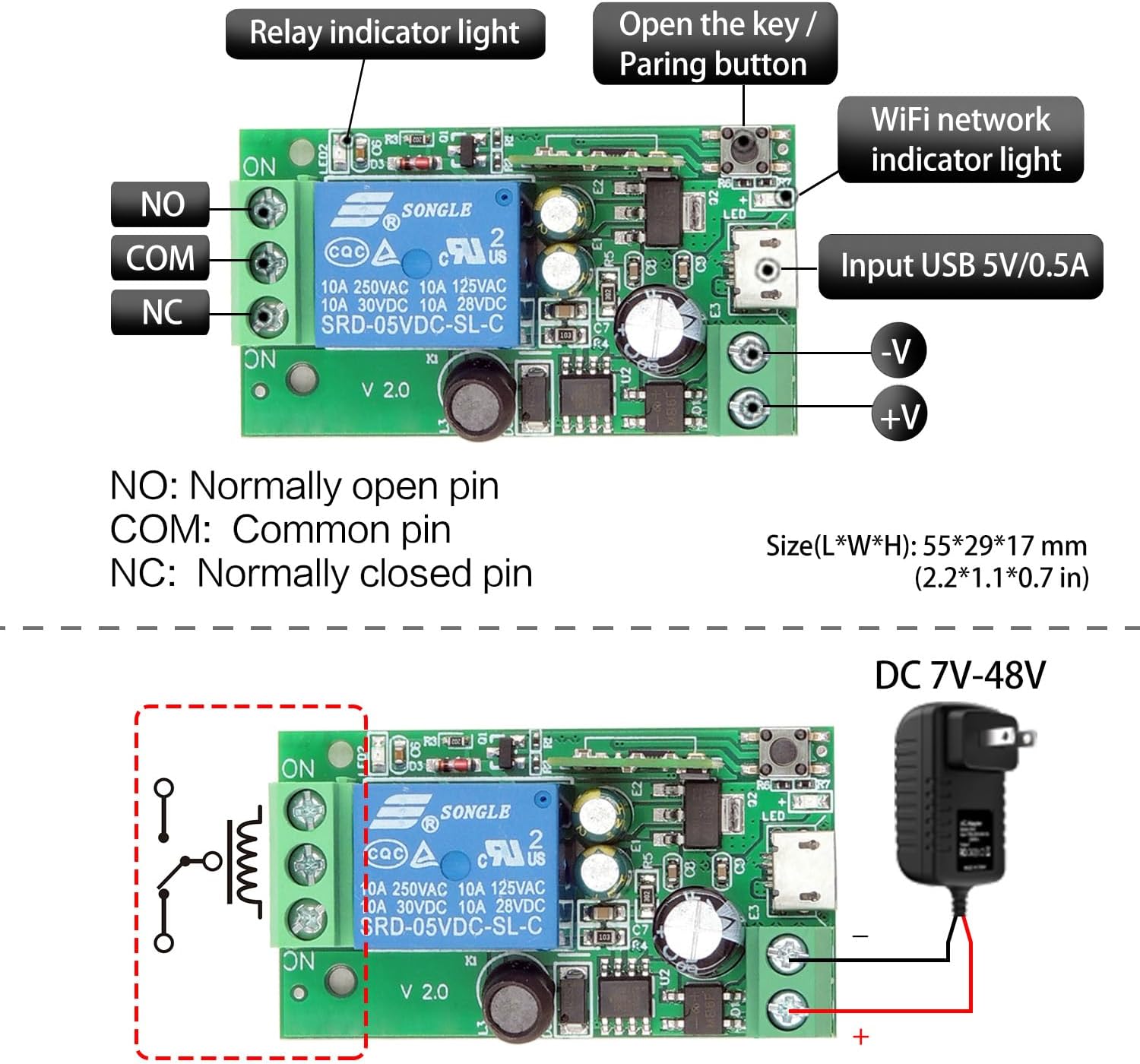
Image 6.1: Detailed view of the module, showing the NO, COM, NC terminals, the pairing button, WiFi indicator, relay indicator, and USB 5V/0.5A input, along with DC 7V-48V power input options.
6.1 Power Input Options
- DC 5V: Connect a 5V DC power supply via the Micro USB port.
- DC 7V-48V: Connect a DC power supply within this range to the +V and -V screw terminals.

Image 6.2: Illustration of the two power input methods: 5V DC via USB and 7V-48V DC via screw terminals.
6.2 Connecting a DC Device
To control a DC device (e.g., a DC motor or LED strip), connect the device's power supply through the relay's COM and NO/NC terminals.

Image 6.3: Wiring diagrams showing how to connect a DC device (top left) and an AC device (top right) using the relay module. Also shows passive output connection (bottom left).
6.3 Connecting a Garage Door Opener
The module can be used to add smart control to existing wired garage door openers. Connect the relay's COM and NO terminals to the wall button/console terminals of your garage door opener.

Image 6.4: A detailed wiring diagram illustrating how to connect the smart relay module to an existing garage door opener for smart control.
7. Applications
The DieseRC 1-Channel WiFi Smart Relay Module is versatile and can be used in various settings, including homes, farms, factories, offices, and laboratories. Common applications include:
- Smart garage door opener systems.
- Electric lock control.
- Lighting control (lamps, LED strips).
- Controlling small appliances or motors.
- DIY remote control switches for various devices.
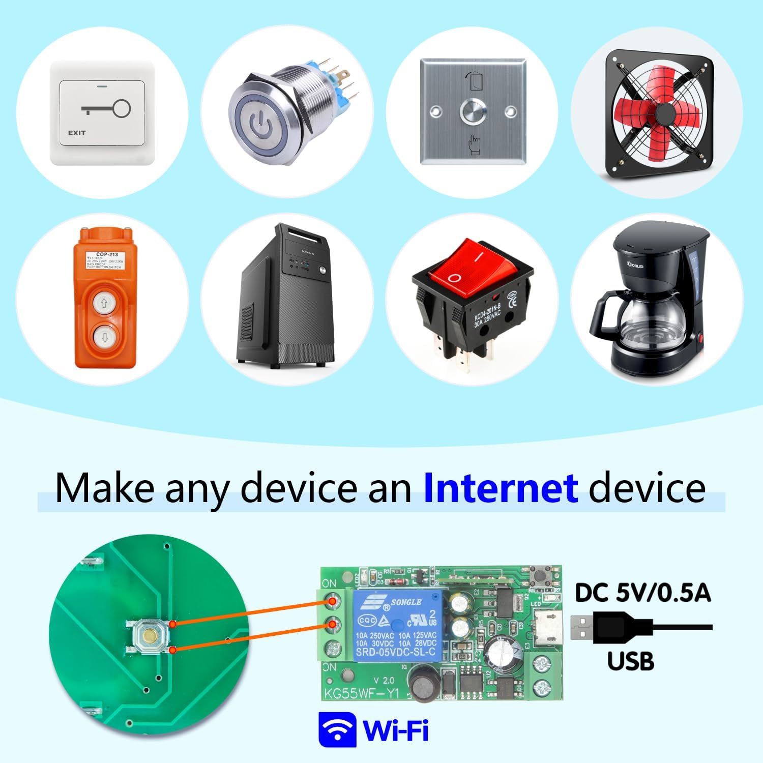
Image 7.1: Examples of devices such as switches, fans, and coffee makers that can be integrated into a smart system using the relay module.
8. Maintenance
- Keep the device dry and away from moisture.
- Avoid exposing the module to extreme temperatures.
- Clean the device with a soft, dry cloth. Do not use harsh chemicals or abrasive cleaners.
- Ensure proper ventilation if installed in an enclosed space.
9. Troubleshooting
| Problem | Possible Cause | Solution |
|---|---|---|
| Device not connecting to WiFi | Incorrect WiFi password, 5GHz network, device too far from router, incorrect pairing mode. | Ensure 2.4GHz WiFi, correct password, move device closer to router, re-enter pairing mode. |
| App cannot control the device | Device offline, app not updated, network issues. | Check device's WiFi connection, update eWelink app, restart router and device. |
| Voice control not working | eWelink account not linked to Alexa/Google Home, incorrect device name, network issues. | Link eWelink account, ensure device name is recognizable, check internet connection. |
| Relay not activating | Incorrect wiring, insufficient power supply, faulty device. | Verify wiring according to diagrams, ensure power supply meets specifications, contact support if issue persists. |
10. Warranty and Support
For warranty information, please refer to the documentation provided with your purchase or contact your retailer. If you encounter any issues that cannot be resolved using the troubleshooting guide, please contact DieseRC customer support for assistance.
Manufacturer: DieseRC
Contact Information: Refer to your product packaging or the official DieseRC website for the latest support contact details.


