
1. Introduction
This manual provides essential information for the proper installation, operation, and maintenance of your XINDUM Interlinked Smoke and Heat Alarm Bundle. This bundle includes two photoelectric smoke alarms and one thermistor heat alarm, designed to provide early warning of fire hazards in your home. For optimal safety, please read these instructions thoroughly before use and retain them for future reference.
2. Package Contents
Verify that all items are present in your package:
- 2 × XINDUM Photoelectric Smoke Alarms (Model: XDS11R / SM11R4)
- 1 × XINDUM Thermistor Heat Alarm (Model: HD11R)
- 1 × Digital Remote Controller
- Mounting Screw Kits
- Double-sided Adhesive Tapes
- User Manual
3. Key Features
- Wireless Interlinking: When one alarm is triggered, all linked alarms will sound, ensuring prompt notification throughout your property.
- Dual Sensor Technology: Photoelectric sensor for smoke alarms (reacts to slow-smoldering fires) and thermistor sensor for heat alarms (triggers above 54℃).
- 10-Year Battery Life: Each alarm is powered by two sealed-in CR14505 Lithium batteries (3200mAh total capacity), providing up to 10 years of standby operation.
- Remote Control Functionality: Conveniently pair, test, and silence alarms from a distance of up to 10 meters.
- Loud Audible Alarm: Produces an 85dB alarm sound to alert occupants.
- LED Indicator: Provides visual status updates for power, alarm, and fault conditions.
- Compact Design: Flat profile (Smoke Alarm: 120mm diameter, 31.5mm height; Heat Alarm: 120mm diameter, 47mm height) for discreet installation.
- Compliance: Compliant with EN14604:2005/AC2008 and BS 5446-2:2003 standards.
4. Safety Information
Please observe the following safety guidelines:
- Do not paint the alarm. Paint can clog the openings and interfere with the sensor's ability to detect smoke or heat.
- Do not attempt to open or repair the alarm. There are no user-serviceable parts inside.
- Test the alarms regularly as instructed in this manual.
- Ensure the alarm is installed in a location where its sound can be heard by all occupants.
- This device is designed for residential use. Consult local fire codes for specific installation requirements.
- The sealed-in battery is not replaceable. Do not attempt to remove or replace it.
5. Installation
Proper placement and installation are crucial for the effective operation of your smoke and heat alarms.
5.1 Recommended Placement
- Smoke Alarms: Install in bedrooms, hallways, living rooms, and on every level of your home, including the basement. For multi-story homes, install at least one smoke alarm on each floor.
- Heat Alarms: Suitable for areas where smoke alarms may cause nuisance alarms due to normal conditions, such as kitchens, garages, and utility rooms. Heat alarms detect rapid temperature increases, not smoke.
Avoid installing alarms in:
- Areas with high humidity (e.g., bathrooms, near showers).
- Near ventilation openings, fans, or air conditioning vents, which can interfere with sensor operation.
- Within 1 meter of cooking appliances.
- In dusty or dirty environments.

Image: Recommended placement for smoke and heat alarms within a home environment.
5.2 Mounting Instructions
You can install the alarms using either the provided screw kits or double-sided adhesive tapes. For a more secure and permanent installation, screw kits are recommended.
- Choose a Location: Select a suitable ceiling or wall location according to the placement guidelines.
- Prepare the Mounting Bracket: Detach the mounting bracket from the alarm unit by twisting it counter-clockwise.
- Screw Installation:
- Mark the two screw holes on the ceiling/wall using the mounting bracket as a template.
- Drill two holes and insert the wall plugs (if necessary).
- Secure the mounting bracket to the ceiling/wall with the provided screws.
- Adhesive Tape Installation (Optional):
- Ensure the mounting surface is clean, dry, and smooth.
- Peel off the protective backing from the double-sided adhesive tape and firmly press it onto the back of the mounting bracket.
- Press the bracket firmly onto the desired ceiling/wall location for at least 30 seconds.
- Attach the Alarm: Align the alarm unit with the mounted bracket and twist it clockwise until it clicks securely into place.

Image: Dimensions of the smoke and heat alarms, illustrating their compact size and mounting options.
6. Operation
Your XINDUM alarms are designed for simple operation. Upon successful installation, the alarms are in standby mode, continuously monitoring for smoke or heat.
6.1 LED Indicator Status
- Green LED Flash (every 45 seconds): Normal operation / Standby mode.
- Red LED Flash & Audible Alarm: Smoke or heat detected.
- Yellow LED Flash (every 45 seconds): Fault or low battery warning.

Image: Detailed view of the smoke alarm components, including the buzzer, multi-function button, LED indicator, and smoke entrance.

Image: Detailed view of the heat alarm components, including the buzzer, multi-function button, LED indicator, and internal battery.
7. Pairing and Interlinking
The alarms in your bundle are pre-linked at the factory. If you purchase additional alarms or need to re-link them, follow these steps:
7.1 Interlinking Process
- Ensure all alarms are powered on.
- On one alarm, press the 'Power/Test/Mute' button three times quickly. The LED indicator will flash rapidly, indicating it is in pairing mode.
- Within 30 seconds, press the 'Power/Test/Mute' button on another alarm three times quickly.
- The alarms will emit a short beep to confirm successful pairing.
- Repeat for all alarms you wish to interlink. A single group can link up to 30 alarms.
The maximum interlinking distance is approximately 100 meters in open outdoor conditions. This distance may be reduced by walls and other obstructions.

Image: Visual representation of the wireless interlinking system, showing communication between smoke alarms, heat alarm, and the remote control.
8. Testing and Silence Function
Regular testing ensures your alarms are functioning correctly. The remote control offers a convenient way to manage your alarms.
8.1 Testing Alarms
Test your alarms weekly to ensure they are operational.
- Using the Remote Control: Press the 'TEST' button on the remote control. All linked alarms should sound.
- Using the Alarm Button: Press and hold the 'Power/Test/Mute' button on any alarm for a few seconds. The alarm will sound, and all linked alarms should also sound.
If an alarm does not sound during testing, refer to the Troubleshooting section.
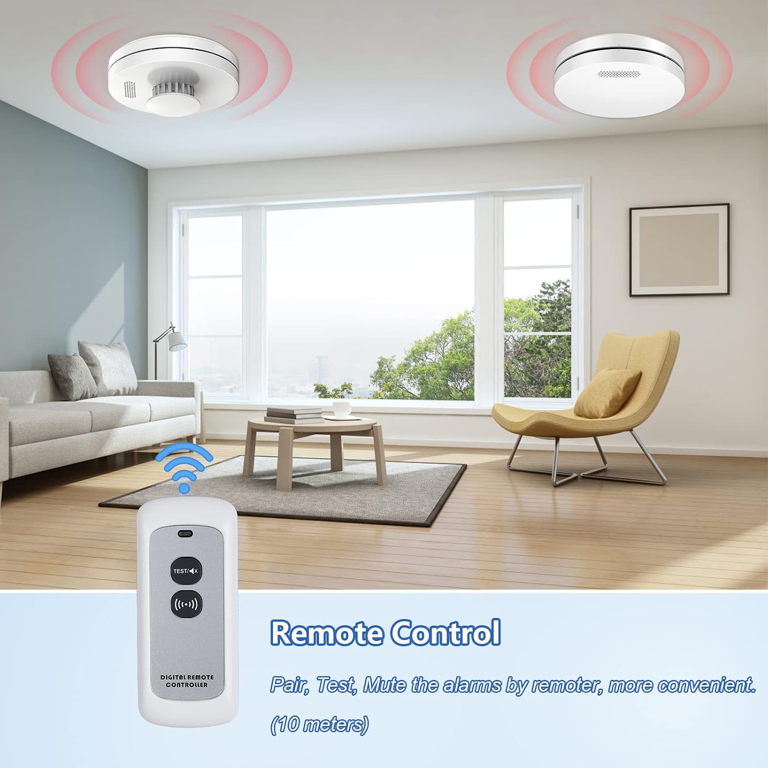
Image: The digital remote controller, used for pairing, testing, and muting alarms from a distance.
8.2 Silence Function (Hush Mode)
In case of a nuisance alarm (e.g., from cooking fumes), you can temporarily silence the alarm.
- Using the Remote Control: Press the 'MUTE' button on the remote control. The alarm will silence for approximately 10 minutes.
- Using the Alarm Button: Press the 'Power/Test/Mute' button on the alarming unit. The alarm will silence for approximately 10 minutes.
After the silence period, the alarm will automatically reset and resume normal monitoring. If the smoke or heat is still present, the alarm will sound again.

Image: A finger pressing the central button on a smoke detector, indicating its use for power, test, and mute functions.
9. Maintenance
Regular maintenance ensures the longevity and reliability of your alarms.
- Cleaning: Dust and debris can accumulate on the alarm and affect its performance. Gently vacuum the alarm's vents and cover with a soft brush attachment at least once a month. Do not use water or cleaning solvents.
- Battery: The alarms feature a sealed-in 10-year lithium battery. No battery replacement is required during the product's lifespan. If the yellow LED flashes and chirps, it indicates a low battery or fault, and the unit should be replaced.
- Replacement: Alarms should be replaced every 10 years from the date of manufacture, or sooner if a fault is indicated.
10. Troubleshooting
If your alarm is not functioning as expected, refer to the following common issues and solutions:
| Problem | Possible Cause | Solution |
|---|---|---|
| Alarm chirps periodically (yellow LED flashes). | Low battery or fault. | The sealed battery is nearing the end of its life or there is an internal fault. Replace the entire alarm unit. |
| Alarm sounds without apparent smoke or heat. | Nuisance alarm (e.g., cooking fumes, steam, dust). | Press the 'MUTE' button on the alarm or remote control to silence it temporarily. Ventilate the area. If false alarms persist, relocate the alarm. |
| Alarm does not sound during test. | Alarm is not powered on, faulty, or battery is depleted. | Ensure the alarm is properly twisted onto its mounting bracket. If it still doesn't work, the unit may be faulty and needs replacement. |
| Linked alarms do not sound when one is triggered. | Alarms are not properly interlinked or out of range. | Re-perform the pairing process (Section 7.1). Ensure alarms are within the effective interlinking range (100m open air, less indoors). Check for obstructions. |
| Remote control is unresponsive. | Remote control battery is depleted. | Replace the battery in the remote control (typically an A23 12V battery). |
11. Specifications
| Feature | Specification |
|---|---|
| Brand | XINDUM |
| Model Number | XDS11R (Smoke Alarm), HD11R (Heat Alarm) |
| Power Source | 2 × CR14505 Lithium Battery (Sealed-in, 3200mAh, 10-year life) |
| Sensor Type | Photoelectric (Smoke Alarm), Thermistor (Heat Alarm) |
| Alarm Loudness | Audible, ≥85dB at 3 meters |
| Operating Humidity | ≤95% RH (non-condensing) |
| Interlinking Quantity | Up to 30 units |
| Interlinking Distance | Up to 100m (open outdoor) |
| Remote Control Distance | Up to 10m |
| Smoke Alarm Dimensions | 120mm (Diameter) × 31.5mm (Height) |
| Heat Alarm Dimensions | 120mm (Diameter) × 47mm (Height) |
| Item Weight | Approximately 452g (total package) |
| Compliance | EN14604:2005/AC2008, BS 5446-2:2003 |
| UPC | 780854889951 |
12. Warranty and Support
XINDUM products are designed for reliability and performance. For any issues or questions regarding your Interlinked Smoke and Heat Alarm Bundle, please contact XINDUM customer support. Refer to your purchase documentation for specific warranty terms and contact information.
We recommend retaining your proof of purchase for warranty purposes.