Introduction
This manual provides detailed instructions for the installation, operation, and maintenance of your PEXMOR Electric Bike Conversion Kit. Please read this manual thoroughly before beginning the installation process to ensure proper setup and safe operation. Retain this manual for future reference.
Package Contents
Carefully unpack all components and verify that all items listed below are included and undamaged. If any items are missing or damaged, please contact customer support.
- Hub Motor Wheel
- LCD Display
- Pedal Assist Sensor (PAS)
- Twist Throttle
- Terminal Box
- Battery Bag (Battery not included)
- Controller
- Cable Ties
- Brake Levers
- Cable Cover
- Transfer Power Cord
- Torque Arm
- Controller Bag
- User Manual
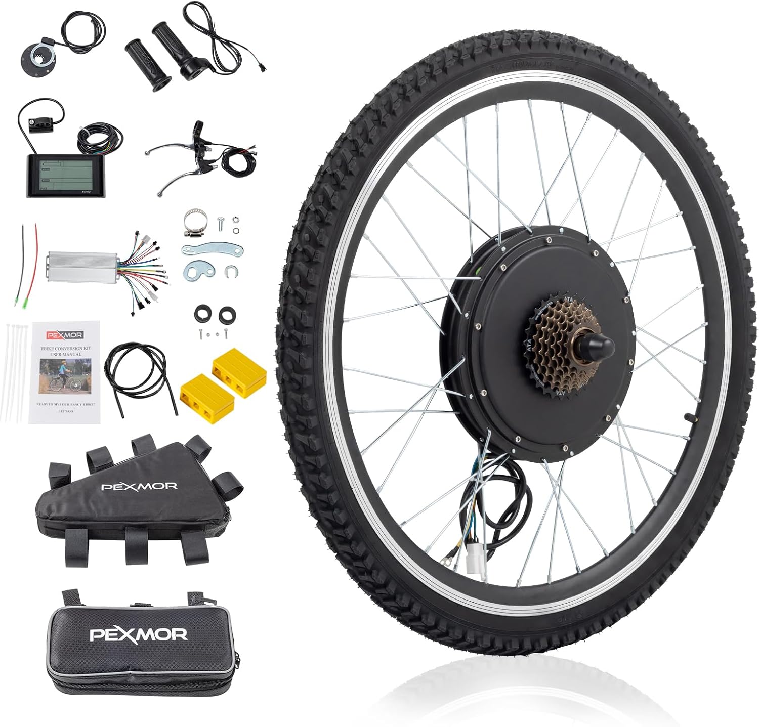
This image displays all the parts included in the PEXMOR Electric Bike Conversion Kit, such as the motor wheel, LCD display, controller, throttle, brake levers, and various cables and accessories.
Setup & Installation
Follow these steps carefully to install your electric bike conversion kit.
1. Pre-installation Checks
Before starting the installation, ensure you have all necessary tools and components. It is recommended to lay out all parts for easy access.
This video demonstrates the initial steps of unboxing the kit and laying out all the components and tools required for the installation process.
2. Rear Wheel Removal & Motor Wheel Installation
This section details the process of removing your bicycle's original rear wheel and installing the new motor wheel.
This video guides you through the complete process of removing the existing rear wheel, transferring necessary components, and installing the new motor wheel.
- Upside down your bicycle for easier access to the rear wheel.
- Loosen the screws of the central shaft on both sides of the rear wheel.
- Loosen the screws of the derailleur to allow for wheel removal.
- Carefully remove the original rear wheel from the bicycle frame.
- Remove the disc-brake and the 7-speed freewheel from your original wheel.
- Install the 7-speed freewheel onto the new motor wheel.
- Install the lining belt around the rim of the motor wheel.
- Install the tire onto the motor wheel.
- Inflate the tire to the recommended pressure.
- Install the motor wheel onto the bicycle frame, ensuring the central shaft is properly seated in the groove.
- Screw on the nuts to secure the motor wheel.
- Install the derailleur back onto the frame and adjust as needed.
- Check the chain for proper tension and alignment.
- Install the disc-brake onto the motor wheel and tighten the screws. Ensure there is no rubbing.
- Put on the nut covers.

This image highlights the powerful 48V 1500W brushless hub motor integrated into the rear wheel, showing its internal components and specifications like torque and RPM.

This diagram provides precise measurements for the motor wheel, including tire width (1.95"/4.95CM), motor hub diameter (250mm/9.84"), axial length (21cm/8.25"), rim diameter (572mm/22.5"), and total tire diameter (26").

This image illustrates the compatible fork dropout sizes for the conversion kit: Front Fork Dropout 3.93" (100mm) with a 3/8" (10mm) notch width, and Rear Fork Dropout 5.12" (135mm). It's crucial to measure your bike's dropout size before installation.
3. PAS Installation
The Pedal Assist System (PAS) enhances your riding experience by providing motor assistance as you pedal.
This video segment demonstrates how to install the PAS sensor onto the bottom bracket of your bicycle.
- Take off the bottom bracket from your bicycle.
- Install the PAS sensor onto the bottom bracket, ensuring it is correctly oriented for forward pedaling.
- Install the crank and pedals back onto the bottom bracket.
- Check if the PAS works correctly by rotating the pedals.
- Make sure there is a proper gap between the PAS and the disc for optimal function.
4. Electrical Control System Connection
Proper electrical connections are crucial for the kit's functionality. Follow the wiring diagram carefully.
This video provides a comprehensive guide to connecting all electrical components, including the controller, display, throttle, brake levers, and battery.
- Connect the controller and all accessories according to the color-coded wires.
- Connect the red, black, and green cables from the controller to the throttle.
- Connect the red, white, and black cables from the controller to the PAS.
- Connect the two sets of red and black cables from the controller to the two brake levers. Ensure the brake levers remain closed when connected.
- Connect the yellow, green, black, blue, and red cable from the controller to the display.
- Connect the cable with the green round head to its corresponding color on the controller. (Notice: Tighten the blue sleeve after inserted).
- Plug the white square plug tightly.
- Connect the black and red round cable to the battery. (Battery with switch is recommended).
- Open the switch on the battery.
- Long press the "M" button to open the display.
- Test the PAS: The PAS will work in Gear "1" and will not work in Gear "0".
- Turn the throttle and check if the motor operates correctly.
- Check the brake levers to ensure they cut power to the motor when engaged.
- Turn off the battery after testing the electric control system.
- Unplug all plugs for final cable management.
5. Handlebar Component Installation
Install the throttle and display onto the handlebar.
This video segment shows how to install the throttle and display unit onto the bicycle's handlebar.
- Replace the original throttle with the new twist throttle.
- Tighten the screw on the throttle to secure it.
- Install the LCD display on the handle.
- Tighten the display by using the screw.
- Connect the controller and accessories, then install and fix the controller and cables according to your preference (e.g., using cable ties or a controller bag).
Operating Instructions
Your PEXMOR Electric Bike Conversion Kit offers multiple riding modes for versatile use.
Riding Modes
- Throttle Mode: Provides power on demand, similar to a motorcycle.
- PAS (Pedal Assist System) Mode: The motor assists your pedaling effort, reducing fatigue.
- Manual Mode: Ride the bike like a traditional bicycle without motor assistance.
- Presets Mode: Utilize pre-set power levels for consistent assistance.

This image visually represents the four distinct riding modes available with the PEXMOR Electric Bike Conversion Kit, allowing riders to choose their preferred level of assistance.
LCD Display Functions
The LCD display provides essential riding information at a glance:
- Battery Level
- Speed
- Distance
- Power Output
- PAS Level

This image provides a clear view of the smart LCD display, detailing the various metrics it shows, such as battery level, current speed, trip distance, power output, and the selected PAS level.
Maintenance
Regular maintenance ensures the longevity and optimal performance of your electric bike conversion kit.
- Regularly check all bolts and connections for tightness.
- Keep the motor and electrical components clean and free from dust and moisture.
- Inspect tires for wear and maintain proper inflation pressure.
- Lubricate the chain and other moving parts as needed.
- Store the bike in a dry, cool place when not in use.
Troubleshooting
If you encounter any issues with your conversion kit, refer to the following common troubleshooting tips:
- No Power: Check battery connection, ensure battery is charged, and verify all electrical connections to the controller and display are secure.
- Motor Not Engaging: Ensure PAS sensor is correctly installed and aligned. Check throttle connection. Verify brake levers are not engaged.
- Display Not Working: Check display cable connection to the controller. Ensure battery is on.
- Unusual Noises: Inspect the motor wheel for any obstructions or loose spokes. Check disc brake alignment.
For more complex issues or if troubleshooting steps do not resolve the problem, please contact PEXMOR customer support.
Specifications
| Feature | Specification |
|---|---|
| Brand | PEXMOR |
| Motor Power | 48V 1500W/1000W Brushless Hub Motor |
| Wheel Size | 26 Inches |
| Max Speed | Up to 37 mph (60km/h) |
| Controller Type | Upgrade 3 Modes Sine Wave Controller |
| Riding Modes | Throttle / Presets / PAS / Manual |
| Max Weight Recommendation | 265 Pounds (120kg) |
| Material | Aluminum |
| Brake Style | Rim Brake (compatible) |
Warranty & Support
PEXMOR products come with a standard manufacturer's warranty. For detailed warranty information, product support, or to inquire about replacement parts, please visit the official PEXMOR website or contact their customer service directly. Keep your purchase receipt as proof of purchase.


