1. Introduction
This manual provides detailed instructions for the safe and effective use of the SAVITA Double-Wire Plug-In Connectors. These connectors are designed for fast and secure low-voltage wire connections, suitable for various household and industrial applications. Please read this manual thoroughly before installation and operation.

Image 1.1: SAVITA Double-Wire Plug-In Connectors. These connectors facilitate quick and reliable electrical connections for low-voltage applications.
2. Safety Information
Always observe the following safety precautions when working with electrical components:
- Ensure power is disconnected before installing or removing connectors to prevent electrical shock.
- Do not exceed the specified voltage and current ratings for these connectors.
- Use appropriate personal protective equipment (PPE) such as safety glasses and insulated gloves.
- Keep connectors away from moisture and extreme temperatures.
- If you are unsure about any electrical work, consult a qualified electrician.
3. Package Contents
Your package should contain the following items:
- 50 x SAVITA Double-Wire Plug-In Connectors
4. Product Specifications
| Feature | Description |
|---|---|
| Model Number | D37039-42 |
| Material | PA66 Nylon (flame retardant insulating material), Copper |
| Wire Voltage Range | 0.3-0.5 square millimeters |
| Workable Wire Type | Solid Wire, Strand Wire |
| AWG Range | 22-20 AWG |
| Inner Diameter (ID) Range | 0.025-0.04 inch |
| Outer Diameter (OD) Range | 0.062-0.08 inch |
| Dimensions (approx.) | 21.8mm (0.85in) Length, 9.8mm (0.38in) Width, 6.15mm (0.24in) Height |
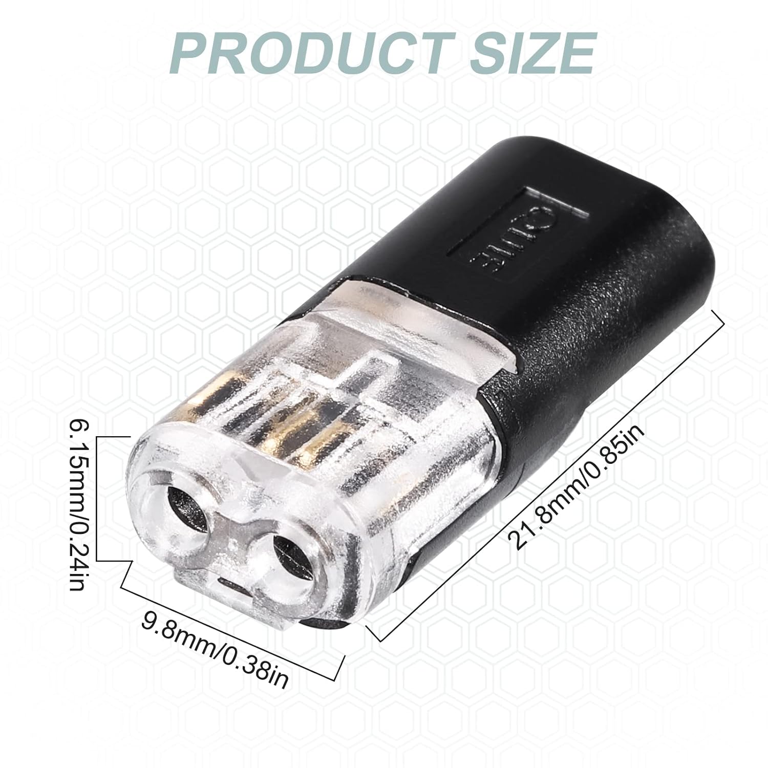
Image 4.1: Product Dimensions. The connector measures approximately 21.8mm in length, 9.8mm in width, and 6.15mm in height.

Image 4.2: Workable Wire Types and Dimensions. The connectors are compatible with both solid and strand wires within the 22-20 AWG range.
5. Setup & Installation
Follow these steps to properly install the double-wire plug-in connectors:
- Prepare Wires: Ensure the wires are stripped to the appropriate length, exposing the conductor without damaging the strands.
- Lift Control Valve: Gently lift the transparent control valve on the connector.
- Insert Wire: Insert the stripped wire into the connector's opening. Ensure the wire is fully seated.
- Secure Connection: Press the control valve down firmly with flat-mouth clips or pliers until it locks into place, securing the wire.
- Connect Halves: Align the two connector halves and push them together until they click, forming a secure connection.
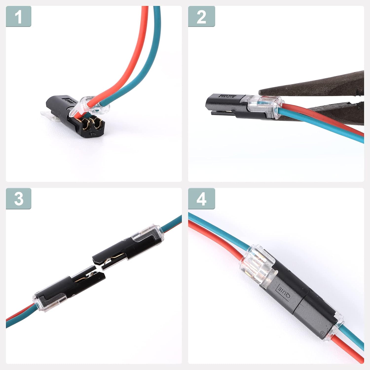
Image 5.1: Installation Steps. This visual guide demonstrates the process from wire insertion to final connection.
Adjusting for Thicker Wires
If you encounter a slightly thicker wire that does not fit easily, you can adjust the connector:
- Locate the small plastic ring inside the wire entry point.
- Carefully cut this ring with scissors to create more space for the wire.
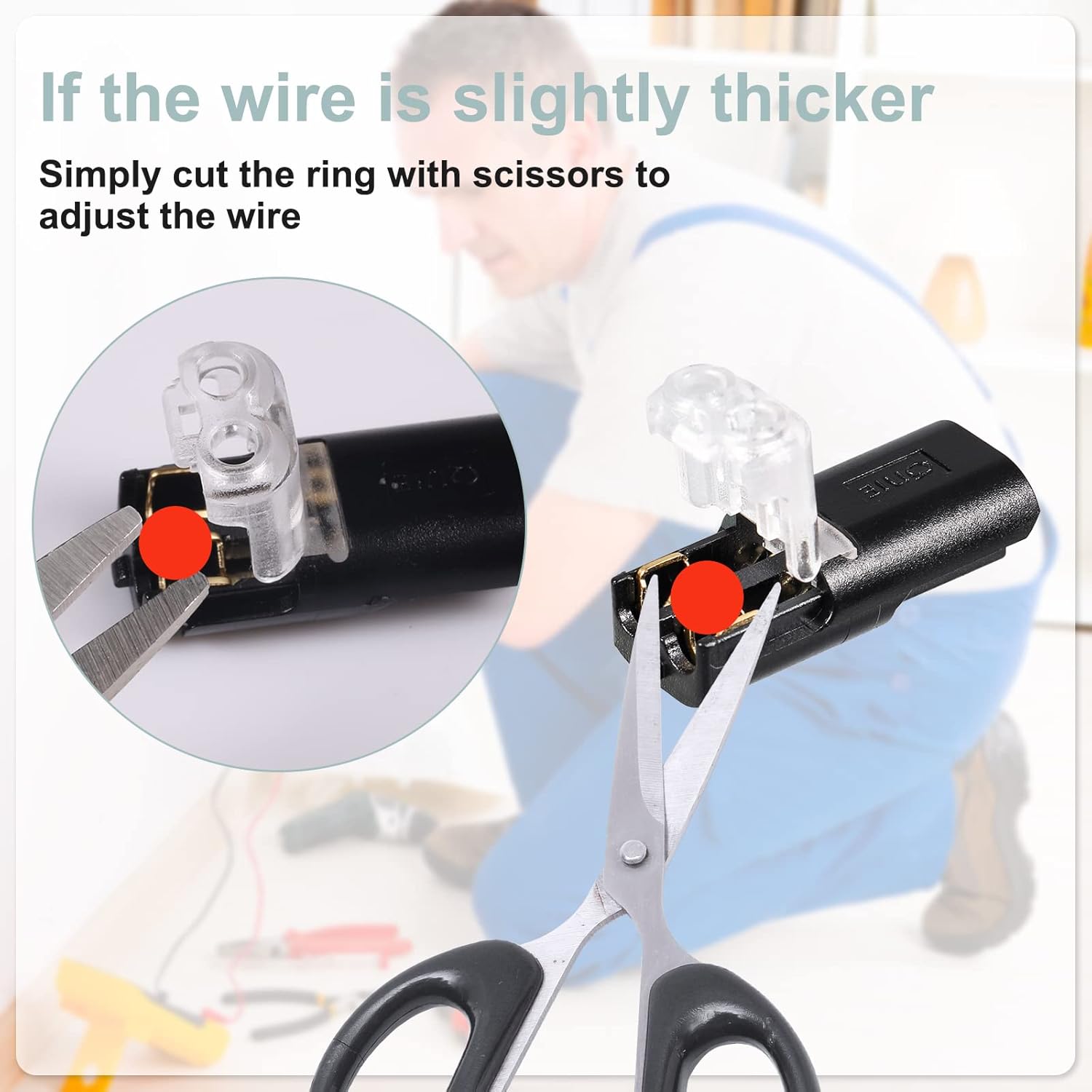
Image 5.2: Wire Adjustment. This image illustrates how to modify the connector for wires that are slightly thicker than standard.
6. Operation
Once installed, the connectors provide a secure and reliable electrical connection. The locking buckle mechanism ensures the connection remains stable. Each connector is designed with independent shrapnel for different wires, allowing for quick and efficient wiring.

Image 6.1: Connector in Use. The image shows a fully connected wire, highlighting the secure and compact nature of the connector.
7. Maintenance
These connectors are designed for durability and require minimal maintenance. To ensure optimal performance and longevity:
- Periodically inspect connections for any signs of damage or loosening.
- Keep connectors clean and free from dust, dirt, and debris.
- Avoid exposing connectors to harsh chemicals or solvents.
- Store unused connectors in a dry, cool place.
8. Troubleshooting
If you encounter issues with your SAVITA Double-Wire Plug-In Connectors, consider the following:
- Loose Connection: Ensure the control valve is fully pressed down and locked. Re-insert the wire if necessary, ensuring it is stripped to the correct length and fully seated.
- Wire Not Fitting: Verify the wire's AWG and diameter are within the specified range (22-20 AWG, ID 0.025-0.04in, OD 0.062-0.08in). If slightly thicker, refer to the 'Adjusting for Thicker Wires' section (Image 5.2).
- No Power Flow: Double-check all connections in the circuit. Ensure the power source is active and the wires are correctly inserted into the connectors. Verify that the wire insulation is not interfering with the connection.
- Connector Damage: If a connector appears physically damaged, replace it immediately. Do not attempt to repair damaged connectors.
9. Wide Application
These wire connectors are versatile and widely used in various low-voltage applications, including but not limited to:
- Ceiling fans
- Sockets and switches
- Speakers
- LED lighting (e.g., strip lights, decorative lights)
- Other common household wiring projects

Image 9.1: Widely Used Applications. The connectors are suitable for a broad range of low-voltage electrical installations.
10. Warranty & Support
For specific warranty information or technical support, please refer to the product packaging or contact SAVITA customer service through the retailer where the product was purchased. Please have your model number (D37039-42) and purchase details ready when contacting support.


