
1. Introduction
The LeTkingok LB06 Process Calibrator is an advanced signal calibration instrument designed for precise measurement and output of various electrical signals. Building upon previous models, the LB06 expands its capabilities to include an extended resistance output range (20-2200 ohms), PT1000 output function, and communication functions such as Modbus master/slave and HART handheld device compatibility. This versatile tool is essential for maintenance and calibration in industrial settings, covering applications for PLC, DCS, ESD systems, field instruments, regulating valves, and frequency converters.
Key features include a built-in disposable fuse for protection against 220V mains insertion, high-precision and high-temperature stability chips for improved performance, and reduced sensitivity of thermal resistance and resistance output to external excitation current, enhancing overall accuracy.
2. Product Overview

Figure 2.1: Front view of the LB06 Process Calibrator, showing the LCD display and control buttons.
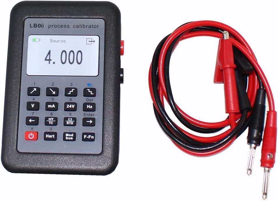
Figure 2.2: The LB06 Process Calibrator shown with its included test leads, essential for connecting to circuits.
2.1 Components
- Main Unit: The LB06 Process Calibrator with LCD display and keypad.
- Test Leads: Red and black leads with banana plugs and alligator clips for various connections.
- USB Cable: For charging and data transfer (if applicable).
- User Manual: Provides detailed instructions for operation.
- Carrying Case: For protection and portability.

Figure 2.3: Included accessories: USB cable, test leads, user manual, and carrying case.
2.2 Device Layout and Dimensions

Figure 2.4: Side view of the LB06 Process Calibrator illustrating its approximate dimensions: 122mm (height) x 80mm (width) x 27mm (thickness).
3. Setup and Powering On
- Charging: Before first use, ensure the calibrator is fully charged using the provided USB cable and a compatible USB power adapter (not included). The charging port is typically located on the side of the device.
- Connecting Test Leads: Insert the banana plugs of the red and black test leads into the corresponding input/output jacks on the calibrator. Ensure a secure connection.
- Power On: Press and hold the red power button (usually located on the bottom left of the keypad) until the LCD screen illuminates.
- Initial Screen: The device will display the main menu or the last used function.
4. Operating Instructions
The LB06 Process Calibrator offers various measurement and output functions. Use the keypad to navigate between modes and adjust values.
4.1 Keypad Functions
- Power Button (Red): Press and hold to power on/off.
- Directional Arrows (Up/Down/Left/Right): Navigate menus and adjust values.
- Function Buttons (V, mA, 24V, Hz, mV/TC, RTD, Hart, Modbus, F-Fn): Select specific measurement or output modes.
- Enter: Confirm selection or value.
- Del: Delete character or return to previous screen.
4.2 Measurement Functions
To measure a signal, select the appropriate function button and connect the test leads to the circuit under test.

Figure 4.1: Examples of LB06 measuring Voltage (V), Current (mA), Millivoltage (mV), and Resistance (Ohm) compared to a reference device.
- DC Voltage (V) Measurement: Select 'V' button. Connect leads in parallel to the voltage source.
- DC Current (mA) Measurement: Select 'mA' button. Connect leads in series with the circuit.
- DC Millivoltage (mV) / Thermocouple (TC) Measurement: Select 'mV/TC' button. Choose specific TC type (e.g., K, J, T) if applicable.
- Resistance (Ohm) / RTD Measurement: Select 'RTD' button. Choose specific RTD type (e.g., Pt100, Pt1000, Cu50) if applicable.
- Frequency (Hz) Measurement: Select 'Hz' button. Connect leads to the frequency source.
4.3 Output Functions
To output a signal, select the desired function and adjust the output value using the directional arrows. Connect the test leads to the device or circuit receiving the signal.

Figure 4.2: Examples of LB06 outputting Voltage (V), Current (mA), Millivoltage (mV), and Resistance (Ohm) compared to a reference device.
- DC Voltage (V) Output: Select 'V' button. Adjust output voltage.
- DC Current (mA) Output: Select 'mA' button. Adjust output current. Supports source, sink, and program modes.
- DC Millivoltage (mV) / Thermocouple (TC) Output: Select 'mV/TC' button. Adjust output mV or select TC type and temperature.
- Resistance (Ohm) / RTD Output: Select 'RTD' button. Adjust output resistance or select RTD type and temperature.
- Frequency (Hz) Output: Select 'Hz' button. Adjust output frequency.
- 24V Loop Power: Select '24V' button to provide 24V loop power for current transmitters.
4.4 Communication Functions (Hart, Modbus)
- HART Communicator: Select 'Hart' button to access HART communication functions for compatible field devices. Refer to the on-screen prompts for specific HART commands.
- Modbus Master/Slave: Select 'Modbus' button to configure the calibrator as a Modbus master or slave. This allows for communication with Modbus-enabled devices. Detailed Modbus protocol settings will be accessible through the menu.
5. Maintenance
- Cleaning: Wipe the device with a soft, dry cloth. Do not use abrasive cleaners or solvents.
- Storage: Store the calibrator in its protective carrying case in a cool, dry place when not in use.
- Battery Care: Recharge the battery regularly, even if not in frequent use, to maintain battery health. Avoid fully discharging the battery for extended periods.
- Fuse Replacement: The device features a built-in disposable fuse for protection. If the device stops functioning due to an overcurrent event, consult a qualified technician for fuse inspection and replacement. Do not attempt to replace the fuse yourself unless explicitly instructed by the manufacturer.
6. Troubleshooting
| Problem | Possible Cause | Solution |
|---|---|---|
| Device does not power on. | Low battery; Power button not held long enough; Internal fault. | Charge the device fully. Press and hold the power button for 3-5 seconds. If issue persists, contact support. |
| Inaccurate readings. | Incorrect function selected; Poor lead connection; Device needs calibration; Environmental interference. | Ensure correct function is selected. Check lead connections. Perform self-calibration if available, or contact support for professional calibration. Operate in a stable environment. |
| No output signal. | Incorrect output mode; Leads not connected properly; Target device not configured correctly. | Verify output mode and value. Check lead connections to the target device. Ensure the target device is ready to receive the signal. |
| Display is blank or frozen. | Software glitch; Low battery. | Attempt a hard reset (power off/on). Charge the device. If unresponsive, contact support. |
7. Specifications
7.1 General Specifications
- Model: LB06
- Brand: LeTkingok
- Power Source: Handheld (Internal Rechargeable Battery)
- Measurement Type: Voltmeter, Ammeter, Ohmmeter, Frequency Meter, Thermocouple, RTD
- Date First Available: September 13, 2015
7.2 Performance Index of Measure

Figure 7.1: Detailed performance specifications for measurement functions.
| Function | Unit | Range | Resolution | Accuracy RD: read number | Note |
|---|---|---|---|---|---|
| DC.V | V | -30~30 | 0.001 | ±0.025%RD ± 0.004V | |
| DC.mA | mA | -30~30 | 0.001 | ±0.025%RD ± 0.004mA | |
| DC.mV | mV | -150~150 | 0.01 | ±0.025%RD ± 0.02mV | |
| Ohm | Ω | 0~999.9 | 0.1 | ±0.025%RD ± 0.2Ω | Lead resistance error is not included in accuracy |
| 1000~2500 | 1 | ±0.025%RD ± 1Ω | |||
| Frequency | Hz | 0~10 | 0.001 | ±0.05%RD ± 2Hz | |
| R | 0~1700℃ | 0.1 | ±0.1%RD ± 3℃ | ||
| S | 0~1600℃ | 0.1 | ±0.1%RD ± 3℃ | ||
| B | 500~1800℃ | 0.1 | ±0.1%RD ± 3℃ | ||
| TC | K | -200~1370℃ | 0.1 | ±0.05%RD ± 0.2℃ | Cold function error is not included in accuracy |
| E | -200~1000℃ | 0.1 | ±0.05%RD ± 0.2℃ | ||
| J | -200~1200℃ | 0.1 | ±0.05%RD ± 0.2℃ | ||
| T | -200~400℃ | 0.1 | ±0.05%RD ± 0.2℃ | ||
| N | -200~1300℃ | 0.1 | ±0.05%RD ± 0.5℃ | ||
| RTD | Pt1000 | -50~300℃ | 0.1 | ±0.1%RD ± 0.5℃ | Lead resistance error is not included in accuracy |
| Pt100 | -200~850℃ | 0.1 | ±0.1%RD ± 0.5℃ | ||
| Cu50 | -50~150℃ | 0.1 | ±0.1%RD ± 1.5℃ |
7.3 Performance Index of Output

Figure 7.2: Detailed performance specifications for output functions.
| Function | Unit | Set range | Step | Accuracy SP: setpoint | Note |
|---|---|---|---|---|---|
| DC.V | V | 0~11 | 0.01/0.1/1 | ±0.025%SP ± 0.004V | |
| DC.mA | mA | source 0~24 | 0.01/0.1/1/4 | ±0.025%SP ± 0.004mA | |
| sink 0~24 | 0.01/0.1/1/4 | ±0.025%SP ± 0.004mA | |||
| program 0~24 | 0.01/0.1/1/4 | ±0.025%SP ± 0.004mA | |||
| DC.mV | mV | 0~110 | 0.1/1/10 | ±0.025%SP ± 0.02mV | |
| Ohm | Ω | 0~400 | 1/10/100 | ±0.025%SP ± 0.3Ω | Lead resistance error is not included in accuracy |
| 400~2200 | 1/10/100 | ±0.025%SP ± 1.5Ω | |||
| Frequency | KHz | 0~10 | 0.01/0.1/1 | ±0.05%SP ± 2Hz | |
| R | 0~1700℃ | 1/10/100 | ±0.1%SP ± 3℃ | ||
| S | 0~1600℃ | 1/10/100 | ±0.1%SP ± 3℃ | ||
| B | 500~1800℃ | 1/10/100 | ±0.1%SP ± 3℃ | ||
| TC | K | -200~1370℃ | 1/10/100 | ±0.05%SP ± 0.2℃ | Cold function error is not included in accuracy |
| E | -200~1000℃ | 1/10/100 | ±0.05%SP ± 0.2℃ | ||
| J | -200~1200℃ | 0.1 | ±0.05%SP ± 0.2℃ | ||
| T | -200~400℃ | 1/10/100 | ±0.05%SP ± 0.2℃ | ||
| N | -200~1300℃ | 1/10/100 | ±0.05%SP ± 0.5℃ | ||
| RTD | Pt1000 | -50~300℃ | 1/10/100 | ±0.1%SP ± 0.5℃ | Lead resistance error is not included in accuracy |
| Pt100 | -200~850℃ | 1/10/100 | ±0.1%SP ± 0.5℃ | ||
| Cu50 | -50~150℃ | 1/10/100 | ±0.1%SP ± 1.5℃ |
8. Warranty and Support
LeTkingok products are designed for reliability and performance. For warranty information, please refer to the documentation included with your purchase or contact LeTkingok customer support directly. Keep your proof of purchase for any warranty claims.
For technical assistance, troubleshooting beyond this manual, or service inquiries, please contact LeTkingok customer support through their official website or the contact information provided in your product packaging.


