1. Product Overview
The DieseRC 433Mhz Wireless Remote Control Switch is a versatile relay receiver system designed for remote control of various electrical devices. It operates on a 433Mhz radio frequency, offering stable and reliable performance with high reception sensitivity. The system supports multiple operating modes and a wide voltage range, making it suitable for diverse applications.

Image 1.1: The DieseRC Wireless Remote Control Switch system, including the receiver module and five keyfob transmitters.
Video 1.1: A demonstration of the relay remote control switch in action, showing momentary and latched modes with a light bulb and an electromagnetic lock, and the reset function.
Key Features:
- 433Mhz RF Wireless Technology: Ensures stable and reliable signal transmission, capable of passing through walls, floors, and doors within a 50-meter open area range.
- Multiple Operating Modes: Supports Momentary, Toggle, Latched, and Delay modes, programmable to suit specific application requirements.
- Wide Voltage Compatibility: The receiver operates safely within a 5V to 30V DC range, making it compatible with 5V, 12V, 24V, and 30V systems.
- High-Quality Relay: Equipped with a 10A relay designed for over 100,000 operations, ensuring durability and stability.
- Potential-Free Contacts: Features Normally Open (NO), Common (COM), and Normally Closed (NC) terminals for flexible wiring.
- Multi-User Control: One receiver can store up to 20 transmitters, and one transmitter can control multiple receivers.
- Secure Coding: Utilizes EV1527 learning code for enhanced security.
2. Package Contents
- 1 x DieseRC 433Mhz Wireless Relay Receiver Module
- 5 x DieseRC Keyfob Transmitters (each with 2x CR2016 batteries installed)
- 1 x Receiver Housing (for protection)
3. Specifications
| Feature | Specification |
|---|---|
| Model Number | 5301+5*KT03 |
| Operating Voltage (Receiver) | DC 5V - 30V |
| RF Frequency | 433Mhz |
| Relay Current Rating | 10 Amps (AC 250V, DC 30V) |
| Contact Type | Normally Open (NO), Common (COM), Normally Closed (NC) |
| Coding Type | EV1527 Learning Code |
| Remote Control Range | Up to 50 meters (open area) |
| Transmitter Battery | 2 x CR2016 (included) |
| Product Dimensions | 0.35 x 0.35 x 0.15 inches (Receiver module) |
4. Safety Information
- Ensure all power is disconnected before performing any wiring to prevent electric shock.
- Verify correct voltage and current ratings for your application to avoid damage to the device or connected equipment.
- Do not expose the receiver module to moisture or extreme temperatures.
- Installation should be performed by individuals familiar with electrical wiring and safety procedures.
5. Setup and Wiring
The receiver module features three terminals for connecting your device: Normally Open (NO), Common (COM), and Normally Closed (NC). It also has terminals for power input (+V and -V).

Image 5.1: Detailed view of the receiver module's components and wiring terminals.
Basic Wiring Principles:
- Power Input: Connect your DC 5V-30V power supply to the +V and -V terminals on the receiver.
- Device Connection: The relay acts as a switch. Connect your device's power line through the COM and either NO or NC terminals, depending on whether you want the device to be ON or OFF when the relay is inactive.
- Normally Open (NO): The circuit is open (device OFF) when the relay is inactive. It closes (device ON) when the relay is activated by the remote.
- Normally Closed (NC): The circuit is closed (device ON) when the relay is inactive. It opens (device OFF) when the relay is activated by the remote.
- Common (COM): This is the common terminal for the relay switch.

Image 5.2: Diagram illustrating the DC 5V-30V safety remote control setup.

Image 5.3: Example wiring configurations for different types of devices.
Example Application: Garage Door Opener
This system can be integrated with existing wired garage door openers. The receiver acts as a companion device, allowing remote control of the garage door.
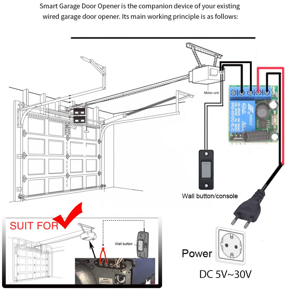
Image 5.4: Wiring for a garage door opener application.
6. Operating Modes and Programming
The DieseRC receiver supports four operating modes: Momentary, Toggle, Latched, and Delay. The default mode is Latched. To change the mode or pair new transmitters, follow the programming steps below. The "Learning Button" on the receiver module is used for programming.
Video 6.1: A detailed guide on how to program the remote control switch for Momentary, Toggle, Latched, and Delay modes, including the reset function.

Image 6.1: Visual representation of the different operating modes.

Image 6.2: Visual guide for programming the receiver to different operating modes.
6.1. Momentary Mode (Mode 1)
In Momentary mode, the relay activates only while the remote button is pressed and held. It deactivates when the button is released.
- Press the Learning Button on the receiver 1 time. The indicator light will turn on.
- Press the desired button on your transmitter (e.g., "ON" button). The indicator light on the receiver will flash, then turn off, indicating successful pairing.
- Test: Press and hold the transmitter button to activate the relay; release to deactivate.
6.2. Toggle Mode (Mode 2)
In Toggle mode, one press of the remote button activates the relay, and a second press deactivates it.
- Press the Learning Button on the receiver 2 times. The indicator light will turn on.
- Press the desired button on your transmitter. The indicator light on the receiver will flash, then turn off, indicating successful pairing.
- Test: Press the transmitter button once to activate; press again to deactivate.
6.3. Latched Mode (Mode 3)
In Latched mode, one button (e.g., "ON") activates the relay, and another button (e.g., "OFF") deactivates it. This mode requires two buttons on the transmitter.
- Press the Learning Button on the receiver 3 times. The indicator light will turn on.
- Press the "ON" button on your transmitter. The indicator light will flash.
- Immediately press the "OFF" button on the same transmitter. The indicator light on the receiver will flash, then turn off, indicating successful pairing.
- Test: Press "ON" to activate; press "OFF" to deactivate.
6.4. Delay Mode (Mode 4, 5, 6, 7)
In Delay mode, the relay activates when the button is pressed and held, and deactivates after a set delay (5, 10, 15, or 20 seconds) once the button is released.
- 5-second Delay: Press the Learning Button 4 times.
- 10-second Delay: Press the Learning Button 5 times.
- 15-second Delay: Press the Learning Button 6 times.
- 20-second Delay: Press the Learning Button 7 times.
- After pressing the Learning Button the required number of times for your desired delay, the indicator light will turn on.
- Press the desired button on your transmitter. The indicator light on the receiver will flash, then turn off, indicating successful pairing.
- Test: Press and hold the transmitter button to activate. Release the button, and the relay will deactivate after the programmed delay.
6.5. Resetting the Receiver
To clear all programmed transmitters from the receiver:
- Press the Learning Button on the receiver 8 times. The indicator light will flash rapidly, then turn off.
- All previously paired transmitters are now cleared. You will need to re-program any transmitters you wish to use.
7. Maintenance
7.1. Transmitter Battery Replacement
The keyfob transmitters are powered by two CR2016 batteries. If the remote control range decreases or the indicator light on the transmitter becomes dim, it may be time to replace the batteries.
- Locate the screw port on the back of the transmitter.
- Carefully open the transmitter casing.
- Remove the old CR2016 batteries and insert new ones, ensuring correct polarity.
- Close the casing securely.
7.2. General Care
- Keep the receiver and transmitters clean and dry.
- Avoid dropping the devices or subjecting them to strong impacts.
- Store in a cool, dry place away from direct sunlight and corrosive materials.
8. Troubleshooting
- Issue: The remote control does not activate the receiver.
- Solution: Check if the transmitter batteries are depleted and replace them if necessary. Ensure the transmitter is within the effective operating range (up to 50 meters in open areas). Verify that the transmitter is correctly paired with the receiver according to the programming instructions for the desired mode.
- Issue: The receiver indicator light does not respond during programming.
- Solution: Ensure the receiver is properly powered (DC 5V-30V). Check the power connections. If the issue persists, try resetting the receiver (press Learning Button 8 times) and then re-program.
- Issue: The device connected to the relay does not turn ON/OFF.
- Solution: Verify that the device is correctly wired to the NO/COM/NC terminals and that the wiring is secure. Check the power supply to the connected device. Ensure the relay is clicking when activated by the remote, indicating it's switching.
- Issue: Short operating range.
- Solution: Replace transmitter batteries. Ensure there are no significant obstructions (thick walls, metal structures) between the transmitter and receiver. Avoid sources of strong RF interference.
9. Warranty and Support
DieseRC products are designed for reliability and performance. For specific warranty details, please refer to the product packaging or contact DieseRC customer support.
For technical assistance or further inquiries, please visit the official DieseRC website or contact their customer service department. Contact information can typically be found on the product packaging or the brand's online store.
Manufacturer: DieseRC


