
1. Introduction
This manual provides detailed instructions for the installation, operation, and maintenance of the IS GY20338 12V/24V DC Digital Temperature Controller. This versatile module offers precise temperature control with a wide range, a 10A one-channel relay, and a waterproof K-Type thermocouple probe. It also features WiFi connectivity for remote monitoring and control via a dedicated mobile application, enhancing convenience and flexibility for various applications.
2. Features
- Wide Temperature Control Range: Supports 18°C to 999°C (or equivalent in °F).
- WiFi APP Control: Monitor and control the device remotely via a mobile application.
- Dual Mode Operation: Selectable heating or cooling modes.
- Multifunctional Settings: Includes delay start, temperature correction, high/low temperature alarm, emergency stop, and sleep functions.
- 10A One-Channel Relay: Provides reliable switching for connected loads.
- Waterproof K-Type Thermocouple Probe: Durable and suitable for various environments.
- Operation Records: View past operation records through the APP.
3. Safety Information
- Ensure the power supply voltage matches the device's requirements (DC 6V-30V).
- Disconnect power before making any wiring connections or performing maintenance.
- Do not exceed the maximum current rating of the 10A relay.
- Install the device in a dry, well-ventilated area, away from flammable materials.
- Handle the K-Type thermocouple probe carefully to avoid damage.
- If you are unsure about any wiring or installation steps, consult a qualified electrician.
4. Product Overview
The IS GY20338 temperature controller consists of a main control board with a display and buttons, and a separate WiFi module. The K-Type thermocouple probe connects to the main board.

Figure 4.1: Overview of the IS GY20338 Digital Temperature Controller, showing the main board, WiFi module, and K-Type thermocouple probe.
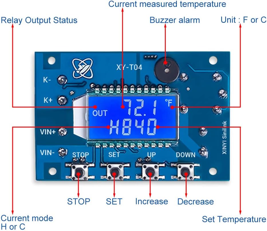
Figure 4.2: Detailed view of the control board with labels for the display (current measured temperature, set temperature, relay output status, current mode, unit), buttons (STOP, SET, UP, DOWN), and buzzer alarm.

Figure 4.3: Wiring diagram illustrating connections for Input DC 6.0V-30V, K-Type Thermocouple, MODBUS Interface, Load Voltage (max DC30V or AC250V with max current 10A), WiFi Status Indicator, and WiFi Configure Button.
5. Setup
5.1 Wiring Connections
- Power Supply: Connect your DC 6V-30V power supply to the VIN+ and VIN- terminals on the main control board. Ensure correct polarity.
- Thermocouple: Connect the K-Type thermocouple probe to the K+ and K- terminals.
- Load: Connect the device you wish to control (e.g., heater, cooler) to the relay output terminals. The relay supports a maximum load of 10A at DC30V or AC250V.
- WiFi Module: The WiFi module is typically pre-connected. Ensure it is securely attached to the main board.
5.2 APP Download and Registration
To utilize the WiFi APP control features, download the 'Sinilink' APP from the 'APP Store' (iOS) or 'Google Play' (Android), or from the Sinilink Official website. An email address is required to register an account within the APP.
5.3 WiFi Pairing
Follow these steps to pair the device with the APP:
- Press and hold the WiFi Configure Button on the WiFi module for 5 seconds to enter pairing mode.
- Router Not Connected: If the router is not connected, the LED on the WiFi module will be ON for 1 second and then cycle.
- Not Connected to Network: If not connected to a network, the LED will alternate fast and slow flashes.
- Waiting for Touch Pairing: The LED indicator will flash 4 times continuously within 1 second.
- Waiting for AP Pairing: The LED indicator will keep fast flashing.
- Paired Successfully: The LED indicator will remain ON.
6. Operating Instructions
6.1 Manual Operation (Buttons)
The device can be operated directly using the buttons on the control board:
- SET Button: Used to enter parameter setting mode and confirm selections.
- UP Button: Increases values or navigates through options.
- DOWN Button: Decreases values or navigates through options.
- STOP Button: Stops the current operation or exits a menu.
6.2 APP Control
Once paired with the APP, you can remotely monitor and control the temperature controller. The APP allows you to:
- View real-time temperature readings.
- Set desired temperature values.
- Switch between heating and cooling modes.
- Configure advanced functions like delay start and alarms.
- Access historical operation records.

Figure 6.1: Mobile application interface for controlling the temperature module, displaying options for automatic and manual modes, temperature settings, and various functions.
7. Parameter Settings
The controller offers several configurable parameters to suit specific needs:
- Temperature Unit: Choose between Celsius (°C) and Fahrenheit (°F).
- Working Mode: Select either heating (H) or cooling (C) mode.
- Delay Start: Set a delay time before the relay activates.
- Temperature Correction: Adjust the temperature reading for calibration.
- High/Low Temperature Alarm: Set thresholds for audible or visual alarms.
- Emergency Stop: A function to immediately halt operations.
- Sleep Mode: Conserves power by entering a low-power state.
Refer to the detailed instructions within the APP or the device's on-screen menu for specific steps on adjusting each parameter.
8. Maintenance
- Keep the device clean and free from dust and moisture.
- Regularly check all wiring connections for tightness and signs of wear.
- Ensure the K-Type thermocouple probe is clean and properly positioned for accurate readings.
- Avoid exposing the device to extreme temperatures or direct sunlight for prolonged periods.
9. Troubleshooting
| Problem | Possible Cause | Solution |
|---|---|---|
| Device not powering on | Incorrect power supply voltage or polarity; loose wiring. | Verify power supply (DC 6V-30V) and connections. Check for correct VIN+ and VIN- polarity. |
| Inaccurate temperature reading | Damaged or improperly connected thermocouple; temperature correction setting. | Check thermocouple connections (K+, K-). Ensure the probe is in the correct environment. Adjust temperature correction if needed. |
| WiFi connection issues | Incorrect pairing procedure; weak WiFi signal; APP registration issues. | Repeat WiFi pairing steps (Section 5.3). Ensure strong WiFi signal. Verify APP account registration. |
| Relay not activating/deactivating | Incorrect temperature settings (set point, hysteresis); load exceeding 10A; faulty relay. | Check set temperature and mode (heating/cooling). Ensure load current is within 10A. Test the relay if possible. |
9.1 Relevant Videos
Video 9.1: This video demonstrates the basic functionality of a 12V electronic temperature controller, showing its display and operation. It provides a visual guide to how such a device functions in a practical setting.
Video 9.2: This video showcases a temperature controller module and digital thermostat switch in action, illustrating its display and response to temperature changes. It helps users understand the visual feedback and basic control aspects of the device.
10. Specifications
| Specification | Value |
|---|---|
| Manufacturer | IS |
| Model Number | GY20338 |
| Input Voltage | DC 6V-30V (Supports 12V, 24V) |
| Temperature Control Range | 18°C to 999°C |
| Relay Output Current | Max 10A |
| Thermocouple Type | K-Type (Waterproof Probe Included) |
| Display Type | LCD |
| Item Weight | 2.08 ounces |
| Package Dimensions | 5.04 x 3.46 x 1.06 inches |
11. Warranty and Support
For any questions regarding the registration and use of the APP, or for product-related inquiries, please contact the manufacturer or seller directly. They provide technical support and after-sales service to ensure your satisfaction.


