
1. Introduction
This manual provides detailed instructions for assembling, setting up, operating, and maintaining your HAWK'S WORK F450 Drone Kit. The F450 is designed for both beginners and experienced users interested in building and customizing their own quadcopter. Please read all instructions carefully before beginning assembly or operation.

Image: The HAWK'S WORK F450 Drone in flight, showcasing its assembled form.
2. What's in the Box
The HAWK'S WORK F450 Drone Kit (Set A) includes the following components:
- Drone Frame: F450 frame, 4 landing skids
- Power System: 4 brushless motors (2212), 4 ESCs (20A), 4 propellers (9450), 1 LiPo battery (4200 mAh)
- Flight Control System: Pixhawk 2.4.8, M8N GPS module, power module, safety switch, buzzer, SD card and card reader, micro-USB cable, various wires, vibration dampening plate, GPS mounting bracket
- RC System: FS-i6X 10-channel transmitter, FS-iA6B receiver
- Other Accessories: English guide book, battery charger, voltage tester, foam adhesives, zip ties

Image: Power System Components

Image: Flight Control System Components

Image: Remote Control System

Image: Accessories and Tools
3. Safety Precautions
- This product is intended for users aged 14 years and above.
- Always follow this guide and any video instructions for assembly and calibration.
- Do not install propellers until all other assembly and calibration steps are complete and verified.
- Users must comply with all local flight-related laws and regulations.
- Ensure the drone is operated in open areas, away from people, animals, and obstacles.
- Always check battery levels and connections before flight.

Image: Quick Start Guide Excerpt with Safety Warnings
4. Assembly Instructions
Follow these steps to assemble your F450 Drone Kit. For a visual guide, refer to the assembly video below.
Video: How to Assemble F450 Drone? DIY a Real Drone. This video provides a comprehensive visual guide for the entire assembly process.
4.1. Step 1: Install Motors
Before installation, identify the two types of motors: clockwise (CW) and counter-clockwise (CCW). CW motors have a hole at the top of the shaft and a white mark on the box. CCW motors have a flat top and no mark on the box. Use M3*8 screws for installation, not the shorter screws found in the motor box.

Image: Motors attached to the drone arms.

Image: Identifying CW and CCW motors.
- Attach the motors to the arms, ensuring the power cords face the inside of the arm.
- Align the screw holes and gently screw in four screws per motor.
- Once all screws are in place, tighten them one by one.
- After installing all four motors, verify there are no errors.
4.2. Step 2: Assemble Plates
Position the arms correctly: the two red arms are at the front, and the two white arms are at the rear. Motors #1 and #2 use CCW motors, while #3 and #4 use CW motors.

Image: Initial frame assembly with arms.

Image: Fully assembled drone frame.
- Install the top plate using four screws per arm (16 screws in total). Gently screw them in first, then tighten.
- Install the bottom plate using two screws per arm (8 screws in total). Gently screw them in first, then tighten.
4.3. Step 3: Assemble Vibration Dampening Plate & Flight Controller
This step involves preparing the vibration dampening system for the flight controller.

Image: Inserting rubber balls into the vibration dampening plate.

Image: Pixhawk mounted on the dampening plate.
- Insert four rubber balls into the holes of the dampening plate to create a shock-absorbing support. Use tweezers to push them in gradually.
- Use two double-sided adhesives to attach the vibration dampening plate to the middle of the top plate.
- Use two more double-sided adhesives to fix the Pixhawk flight controller onto the middle of the vibration dampening plate. Ensure the arrow on the Pixhawk points towards the front of the drone.
4.4. Step 4: Install ESCs
The Electronic Speed Controllers (ESCs) regulate motor speed. The motor rotation direction is determined by the order of the three wires connected to the ESC. For now, connect them randomly; adjustments can be made during commissioning.

Image: ESCs ready for installation.
- Connect the ESCs to the motors.
- Insert the XT60 plug for power supply.
- Route the Dupont wires through the vibration dampening plates and insert them into the MAIN OUT ports of the Pixhawk (e.g., port #1 for motor #1). Ensure the black wire is on top.
- Secure the ESCs and XT60 connectors to the drone arms using zip ties. Ensure they are firmly secured. Motor connections do not need to be secured at this stage as wiring sequence may be adjusted later.
4.5. Step 5: Install GPS Bracket & Module
The GPS module is crucial for stable flight and advanced features.
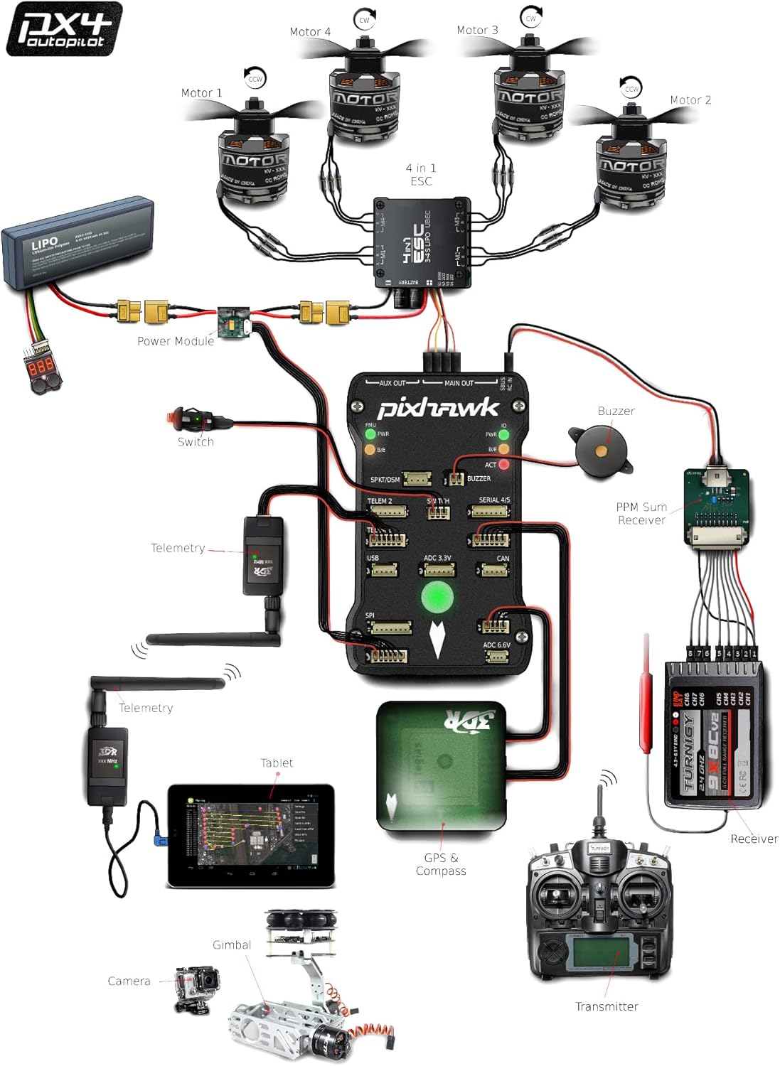
Image: GPS module and bracket components.
- Assemble the GPS bracket by following the provided demonstration steps.
- Unscrew two screws from the top plate, then fix the GPS bracket base using these screws.
- Fix the GPS module to the plate with double-sided tape, ensuring the arrow direction faces forward.
- The GPS module has two wires; plug them into the GPS and I2C sockets on the Pixhawk.
4.6. Step 6: Install Receiver, Buzzer & Safety Switch
These components provide control input, audio alerts, and a safety mechanism.
- Plug the 3-pin Dupont cable from the receiver's PPM port into the RC port of the Pixhawk. Ensure the white wire is on top.
- Plug the buzzer wire into its corresponding port on the Pixhawk and fix the buzzer on an arm using double-sided tape.
- Insert the safety switch wire into its corresponding port on the Pixhawk and place the switch in a convenient position.
- Use three zip ties to firmly fix the safety switch.
5. Setup and Calibration
After physical assembly, the drone requires software setup and calibration using a ground control station like Mission Planner or QGroundControl. This involves:
- ESC Calibration: This is critical for ensuring all motors spin correctly and synchronously. Incorrect calibration can lead to unstable flight or motor issues.
- Pixhawk Calibration: Calibrate the accelerometers, compass, and other sensors for accurate flight control.
- Motor Direction: Verify that each motor spins in the correct direction (CW or CCW) as required for quadcopter stability. Adjust wiring if necessary.
- Radio Calibration: Calibrate your FS-i6X transmitter with the Pixhawk to ensure correct control input.
Image: Mission Planner and QGroundControl interfaces for drone setup.
6. Basic Flight Instructions
Once your drone is fully assembled and calibrated, you can proceed with basic flight operations. Always ensure you are in a safe, open area.
Video: Remote a F450 Drone by FS-I6X. This video demonstrates basic flight procedures.
6.1. Pre-Flight Checklist
- Install Propellers: Motors #1 and #2 use propellers with silver caps. Motors #3 and #4 use propellers with black caps. Tighten them firmly by hand.
- Transmitter Power On: Turn on your FS-i6X transmitter. Pull the throttle stick to its lowest position and ensure all switches are in their original positions.
- Battery Connection: Secure the drone battery with a tie and connect it to the power module.
- Voltage Check: Plug in the voltage tester and ensure the battery is at 3.6 or 3.7 volts per cell.
- Safety Switch: Turn on the safety switch by pressing and holding it for about 2 seconds.
- LED Status Check: Observe the Pixhawk LED. A flashing green light indicates normal GPS function and that the HOME position has been recorded. A flashing blue light indicates the GPS cannot locate.
6.2. Takeoff and Basic Maneuvers
- Arm the Aircraft: Take the left stick to the bottom-left position for about 4 seconds. The propellers will start to rotate, and the drone will be in standby mode.
- Change Flight Mode: Change the flight mode switch to 'Loiter'.
- Takeoff: Slowly push the throttle stick (left stick) to about 50% to initiate takeoff.
- Movement: Use the right stick to move the drone left, right, forward, and backward. Use the left stick to fly up, fly down, and rotate left or right.
7. Operating Modes
The F450 drone supports various flight modes for different operational needs:
- Loiter Mode: In this mode, the drone can maintain a fixed height and position. This is effective under conditions of high GPS positioning accuracy and low wind.
- RTL (Return to Launch) Mode: When activated, the drone will automatically return to its recorded HOME position. It is crucial to use RTL only when the HOME position is accurately located in open areas and there are no obstacles between the drone's current position and the HOME point.
Image: The F450 drone's modular design allows for integration of additional components like cameras and single-board computers.
8. Maintenance
Regular maintenance ensures the longevity and safe operation of your F450 drone:
- Inspect propellers for any damage (cracks, chips) before each flight. Replace damaged propellers immediately.
- Check all wiring connections for looseness or damage. Secure any loose connections.
- Keep motors and ESCs clean and free from debris.
- Regularly check battery health and ensure proper charging and storage.
- Ensure all screws are tightened appropriately.
9. Troubleshooting
Here are some common issues and their potential solutions:
- Motors not spinning/syncing: This often indicates an issue with ESC calibration. Ensure ESCs are correctly calibrated with the Pixhawk. Verify motor wiring sequence if rotation direction is incorrect.
- No GPS Fix (Blue LED): Ensure the GPS module is correctly connected and has a clear view of the sky. Operate in an open area away from tall buildings or interference.
- Drone not powering on: Check all power connections, especially the battery and power module. Ensure the safety switch is pressed correctly.
- Unstable flight: Re-check all Pixhawk calibrations (accelerometer, compass, radio). Ensure propellers are correctly installed and undamaged.
10. Specifications
| Brand | HAWK'S WORK |
| Model Name | WORK F450 |
| Special Feature | Integrated GPS |
| Age Range (Description) | Adult |
| Color | Red and Black |
| Connectivity Technology | USB |
| Skill Level | Beginner |
| Battery Capacity | 4200 Milliamp Hours |
| Maximum Range | 600 Meters |
| Battery Cell Composition | Lithium Polymer |
| Item Dimensions L x W x H | 14.17"L x 7.48"W x 9.84"H |

Image: F450 Frame Dimensions
11. Warranty and Support
HAWK'S WORK offers a free replacement for quality problems within 3 months of purchase. For technical support or after-sales service, please contact the seller directly.


