1. Introduction
This manual provides essential instructions for the safe and efficient operation of your HKS 2.2KW 3HP 110V Variable Frequency Drive (VFD) Controller. Please read this manual thoroughly before installation, operation, or maintenance to ensure proper usage and prevent damage or injury.
2. Safety Information
WARNING: Electrical shock hazard. Only qualified personnel should perform installation and maintenance.
- Ensure power is disconnected before any wiring or maintenance.
- Proper grounding is essential for safe operation.
- Do not operate the VFD with damaged wiring or components.
- Verify input voltage matches VFD specifications (AC 110V, 95-135V).
- Delta (Δ) connection is recommended for motor wiring.
- If your motor is heavy-duty, consider a higher power VFD.
- Consult customer service for complex requirements or before connecting to specific load equipment.
3. Product Overview
The HKS VFD is designed to control the speed of 3-phase motors from a single-phase 110V input. It features an intuitive display and various protection mechanisms.
3.1 Key Features
- Power: 2.2KW (3HP)
- Input Voltage: AC 110V (95-135V)
- Output Voltage: 110VAC ±15%
- Input Current: 20A
- Output Current: 30A
- Input Frequency: 40-60 HZ
- Output Frequency: 0-400 HZ
- Input Phase: 1 phase
- Output Phase: 3 phase
- Intuitive Display and Control Panel (detachable for remote control)
- Multiple Protection: Overload, Fuse, Overvoltage, Low Voltage, Restart, Stall, Short Circuit, Overheat.
- Low Noise and Electromagnetic Interference.
3.2 Product Components
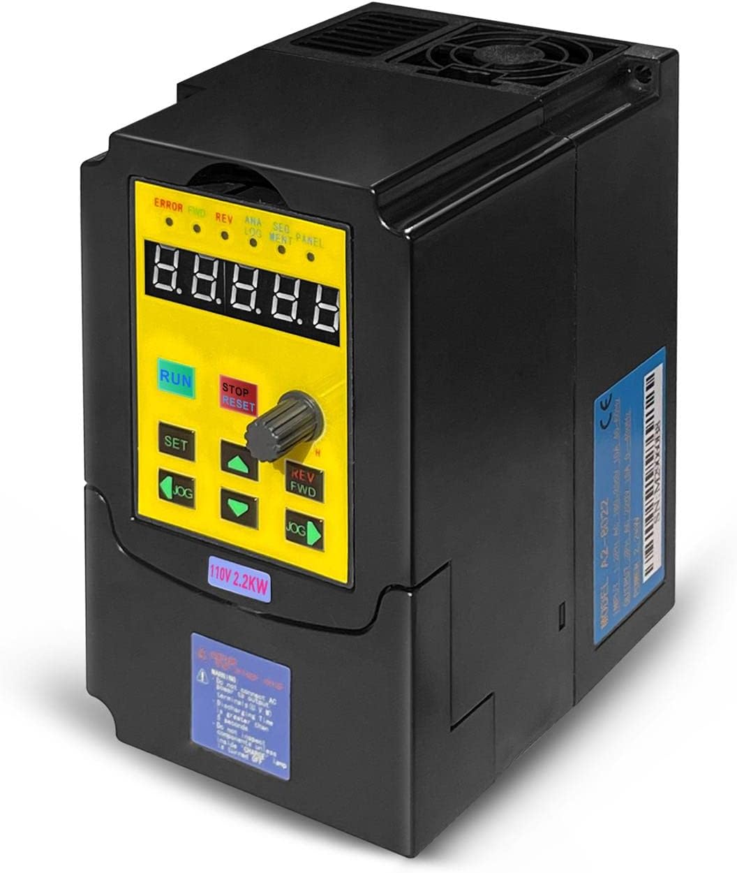
Figure 1: Front view of the HKS VFD Controller, showing the digital display and control buttons.
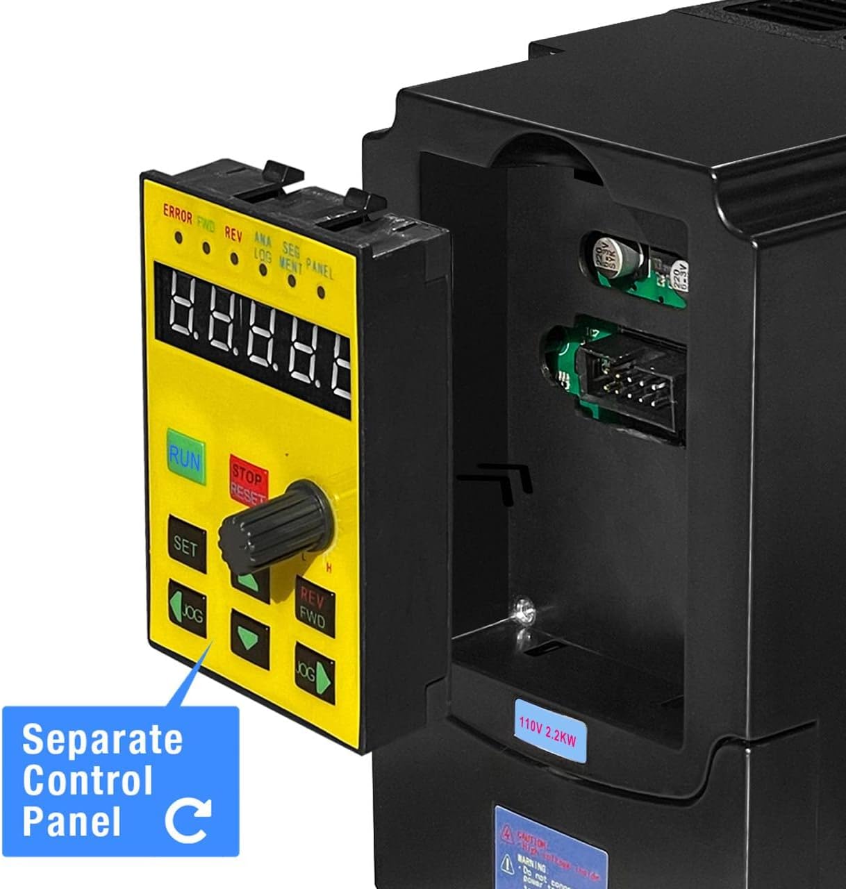
Figure 2: The VFD Controller with its detachable control panel, illustrating remote control capability.
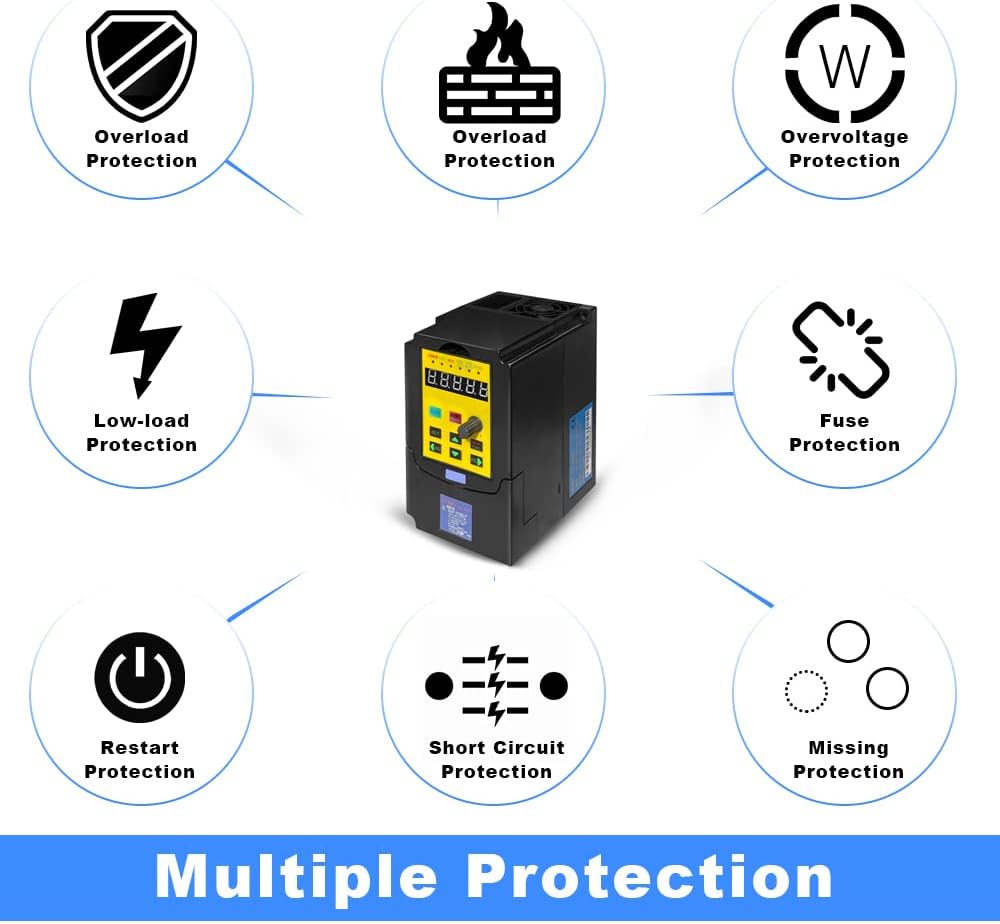
Figure 3: Visual representation of the VFD's multiple protection features, including overload, overvoltage, and short circuit protection.
4. Setup and Installation
4.1 Wiring Connections
Ensure all power is off before making any electrical connections. Refer to the wiring diagram below for correct input and output connections.

Figure 4: Simplified wiring diagram showing connection from a circuit breaker to the VFD (L, N terminals) and then to a 3-phase motor (U, V, W terminals).

Figure 5: Detailed basic connection diagram for the VFD, including control signal inputs and relay outputs. Note: For single-phase input, connect to L and N terminals; other input phase terminals remain vacant. Confirm input voltage is within the allowable range.
Important Notes:
- For single-phase power input, connect to terminals L and N. The other input phase terminal should remain vacant.
- Always confirm the input voltage is within the specified range (AC 95-135V) for proper operation.
- External resistance is not supported. Adjust parameters to achieve similar functionality if needed.
5. Operating Instructions
5.1 Control Panel Functions

Figure 6: Diagram of the VFD control panel, detailing each button and indicator light.
| Button | Description |
|---|---|
| RUN/STOP | Press to start the inverter when idle, press again to stop the inverter. |
| STOP/RESET | Stops the inverter if running; resets if a fault occurs; returns to parent menu. |
| REV/FWD | Changes the inverter's direction (forward/reverse). Also functions during runtime. |
| SET | Enters the menu setting. In a sub-menu, saves the parameter and moves to the next item. |
| ▲ / ▼ | Menu item selection and sub-item data modification. |
| JOG | Menu item content modification selection or inverter jogging button. |
| Adjustment Knob | Controls the frequency. |
| Content | Description |
|---|---|
| ERROR | Fault indicator. |
| FWD | Clockwise rotation indicator. |
| REV | Anticlockwise rotation indicator. |
| ANALOG | Analog input frequency indicator. |
| SEGMENT | Segment input frequency indicator. |
| PANEL | Panel input frequency indicator. |
| Digital LCD | Inverter runtime frequency. If inverter stops, it flashes. The display data is given by "Pn01" data. |
5.2 Basic Operation Sequence
- Ensure all wiring is correct and secure.
- Apply power to the VFD.
- Use the Adjustment Knob to set the desired output frequency.
- Press the RUN/STOP button to start the motor.
- To change direction, press the REV/FWD button.
- To stop the motor, press the RUN/STOP button again or the STOP/RESET button.
6. Maintenance
Regular maintenance ensures the longevity and optimal performance of your VFD.
- Keep the VFD clean and free from dust and debris.
- Ensure adequate ventilation around the unit. The product casing is designed with multiple holes for cooling.
- Periodically check all wiring connections for tightness and signs of wear.
- Inspect the cooling fan for obstructions and proper operation.
- Avoid operating the VFD in environments with excessive moisture or corrosive gases.

Figure 7: Illustration of the VFD's cooling design, showing airflow for heat dissipation.
7. Troubleshooting
This section provides solutions to common issues. For problems not listed here, contact customer support.
| Problem | Possible Cause | Solution |
|---|---|---|
| VFD does not power on | No input power; incorrect wiring; blown fuse. | Check power supply; verify wiring (L, N); inspect internal fuse. |
| Motor does not run | Incorrect motor wiring; VFD in STOP mode; fault condition. | Verify U, V, W connections to motor; press RUN; check ERROR indicator and reset if needed. |
| Overload error | Motor drawing too much current; VFD undersized for load. | Reduce motor load; check motor for issues; consider a higher power VFD. |
| Overvoltage/Low voltage error | Input voltage outside specified range. | Verify input voltage (AC 95-135V) with a multimeter. |
| Motor stalls | Insufficient torque; rapid acceleration setting. | Adjust acceleration time; ensure VFD is appropriately sized for the motor and load. |
If an error occurs, the ERROR indicator will illuminate. Press the STOP/RESET button to clear the fault after addressing the cause.
8. Specifications
| Parameter | Value |
|---|---|
| Model | VFD-110V |
| Power | 2.2KW (3HP) |
| Input Voltage | AC 110V (95-135V) |
| Output Voltage | 110VAC ±15% |
| Input Current | 20A |
| Output Current | 30A |
| Input Frequency | 40-60 HZ |
| Output Frequency | 0-400 HZ |
| Input Phase | 1 phase |
| Output Phase | 3 phase |
| Item Weight | 2.44 pounds |
| Package Dimensions | 7.56 x 7.01 x 5.47 inches |

Figure 8: Dimensions of the HKS VFD Controller: 5.5 inches (height), 4.4 inches (depth), 3.3 inches (width).
9. Warranty and Support
For warranty information and technical support, please refer to the manufacturer's official documentation or contact HKS customer service directly.
When contacting support, please provide your product model (VFD-110V) and a detailed description of the issue.


