
Cooler Master NR200P MAX
Cooler Master NR200P MAX Mini-ITX PC Case Instruction Manual
Model: NR200P MAX (NR200PV2-MCNN85-SL0)
Introduction
The Cooler Master NR200P MAX is a compact Mini-ITX PC case designed to streamline the PC building experience. This manual provides detailed instructions for assembling your system, ensuring optimal performance and ease of use. The MAX series offers a ready-to-go package with pre-installed components, including a 280mm All-in-One (AIO) liquid cooler and an 850W SFX power supply, to simplify the build process.
Video: Cooler Master NR200P MAX Introduction. This video provides a brief overview of the NR200P MAX case and its features.
Product Overview
The NR200P MAX features a sleek, compact design with a focus on thermal performance and component compatibility. Its small 18.25L footprint accommodates Mini-ITX motherboards and supports high-end graphics cards through vertical mounting.
Key Features:
- Compact ITX Design: Optimized for Mini-ITX motherboards with an 18.25L volume.
- Vertical GPU Mounting: Supports GPUs up to 357.6mm in length, including a bundled PCIe 4.0 riser cable.
- Integrated Cooling: Features a pre-installed 280mm top-mounted AIO liquid cooler.
- High-Efficiency PSU: Includes an 850W SFX Gold ATX 3.1 power supply with custom short-length cables.
- Tool-Free Access: Quick-release pins and removable panels for easy installation and maintenance.
- Socket Compatibility: Redesigned brackets for AM5/AM4 and LGA 1851/1700 platforms.

Image: A comparison image showing the compact size of the Cooler Master NR200P MAX (Mini-Tower) next to a standard Mini-ITX motherboard, with dimensions indicated.
Dimensions:
The case measures approximately 14.84 x 7.28 x 11.49 inches (377 x 185 x 292 mm).

Image: Side view of the Cooler Master NR200P MAX case with dimensions labeled: 14.84 inches (length), 7.28 inches (width), and 11.49 inches (height).
Front I/O Ports:
- 1x USB 3.2 Type-C (20Gb/s)
- 2x USB 3.2 Gen 1 Type-A
- 1x Combination Headphone/Microphone Jack
- Power Button

Image: Close-up view of the front I/O panel of the Cooler Master NR200P MAX, showing the USB 3.2 Type-C port, two USB 3.2 Type-A ports, and the audio jack.
Video: NR200P MAX Series. This video highlights various features and design aspects of the NR200P MAX.
Setup and Installation
1. Preparing the Case
The NR200P MAX features a tool-free design for easy access to internal components. Follow these steps to prepare the case for your build:
- Remove Side Panels: Gently pull the side panels outwards from the bottom edge. They are secured with quick-release pins.
- Remove Top Panel: Lift the top panel upwards to detach it. This provides access to the pre-installed AIO cooler.
- Remove Front Cable Cover: Unlock the toolless latches on the corner cable cover and rotate it to remove. This provides access for cable management.
Video: Cooler Master Ncore 100 MAX Installation Tutorial. This video demonstrates the removal of outer panels and cable covers for case preparation.

Image: Exploded view of the Cooler Master NR200P MAX showing all panels and internal components detached, highlighting the modular design.
2. Motherboard Installation
The NR200P MAX supports Mini-ITX motherboards. Ensure your CPU, RAM, and M.2 SSDs are installed on the motherboard before placing it into the case.
- Install CPU Cooler Brackets: Depending on your CPU socket (LGA 115x/1200/1700/1851 for Intel or AM4/AM5 for AMD), attach the appropriate mounting brackets to the CPU pump block. Refer to your motherboard's manual for CPU installation and thermal paste application.
- Place Motherboard: Carefully slide the motherboard into the case, rear I/O panel first, aligning the screw holes.
- Secure Motherboard: Tighten the four screws to secure the motherboard.
- Connect Cables:
- Install the 8-pin EPS cable (CPU power).
- Install the 24-pin EPS cable (main motherboard power).
- Connect front panel connectors (Power button, USB, HD Audio).
- Connect the riser cable to the motherboard's PCIe slot.
- Connect the AIO pump's 3-pin header to the motherboard's "AIO PUMP" header.
- Connect the radiator fan's 4-pin cable to the "CPU_FAN" header.
- Connect the rear fan's 4-pin cable to the "CHA_FAN" or "Chassis fan" header.

Image: Cooler Master NR200P MAX showing redesigned brackets for AMD (Ryzen AM5/AM4) and Intel (LGA 1851/1700) platforms.
3. Graphics Card Installation
The NR200P MAX supports vertical GPU mounting. The case can accommodate triple-slot graphics cards up to 357.6mm in length.
- Prepare GPU Mounting: If your GPU is between 337-357mm in length, you may need to adjust the case's internal structure by moving the right foot one position over and removing the riser PCI slot screws.
- Install GPU: Carefully insert your graphics card into the PCIe riser slot, ensuring it is properly seated.
- Secure GPU: Tighten the GPU screws to firmly hold the card in place.
- Connect GPU Power: Install the 16-pin power connector (450W or 600W depending on GPU) to the GPU, ensuring it is properly seated.

Image: Internal view of the Cooler Master NR200P MAX showing a large graphics card vertically mounted, with the PCIe riser cable visible.
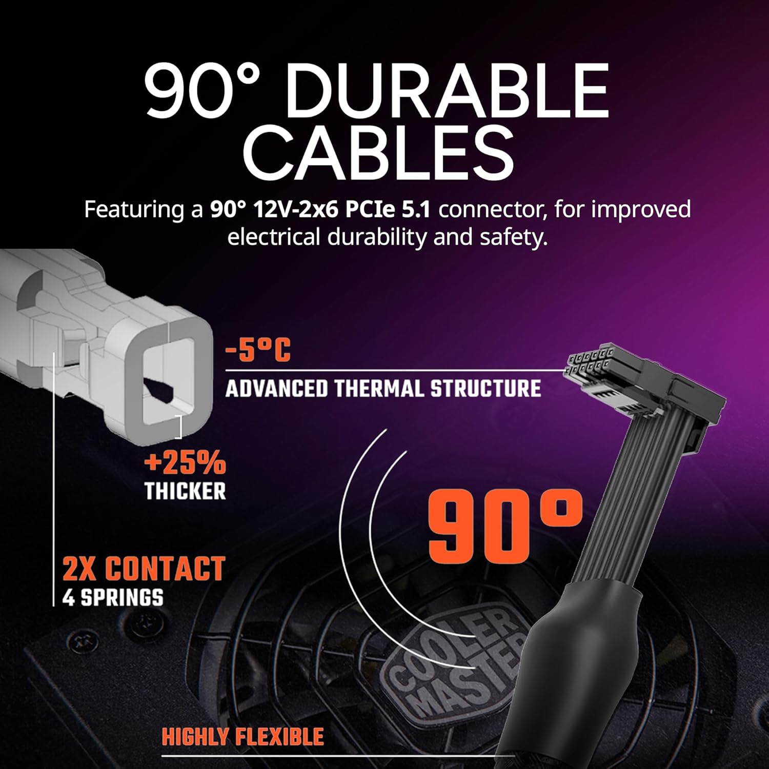
Image: Close-up of the 90-degree 12V-2x6 PCIe 5.1 connector, highlighting its durable design and improved electrical safety.
4. Storage Drive Installation (2.5" SSD)
The case supports a single 2.5" SSD. For additional storage, utilize M.2 slots on your motherboard.
- Attach Mounting Pins: Secure the toolless SSD mounting pins to your 2.5" SSD.
- Install SSD: Fit the pins into the bottom panel rubber rings, aligning the back two pins first.
- Connect Cables: Connect the SATA power cable from the PSU and the SATA data cable to the SSD.

Image: Internal view of the Cooler Master NR200P MAX showing a 2.5-inch SSD installed at the bottom of the case.
5. Final Assembly
Once all components are installed and cables are managed, reassemble the case panels.
- Reinstall Front Cable Cover: Lock the front cable cover back into place.
- Reinstall Top Panel: Place the top panel back onto the case and press down until it clicks securely.
- Reinstall Side Panels: Align the side panels and push them gently until the quick-release pins engage.
Operating Instructions
To power on your Cooler Master NR200P MAX system, press the large power button located at the bottom corner of the front panel. Ensure all external peripherals (monitor, keyboard, mouse) are connected before powering on.
Maintenance
Regular maintenance helps ensure optimal performance and longevity of your PC. The NR200P MAX features integrated dust filters in its mesh panels.
- Dust Filter Cleaning: Periodically remove the mesh side panels and top panel to clean any accumulated dust from the filters. Use compressed air or a soft brush.
- Component Cleaning: With the panels removed, gently clean dust from internal components like fans, heatsinks, and the GPU.
- Cable Management: Ensure cables are neatly routed to maintain optimal airflow.
Troubleshooting
- System Not Powering On:
- Check all power connections to the motherboard, CPU, and GPU.
- Ensure the power supply switch is in the ON position.
- Verify the front panel power button connector is correctly attached to the motherboard.
- No Display Output:
- Ensure your monitor cable is securely connected to the graphics card (or motherboard if using integrated graphics).
- Verify the graphics card is properly seated in its PCIe slot and the power connector is secure.
- Check that the PCIe riser cable is correctly installed.
- Overheating Issues:
- Ensure all fans (AIO, chassis, GPU) are spinning correctly.
- Check for dust buildup on filters and heatsinks.
- Verify proper application of thermal paste on the CPU.
Specifications
| Feature | Detail |
|---|---|
| Brand | Cooler Master |
| Model Name | NR200P MAX |
| Item Model Number | NR200PV2-MCNN85-SL0 |
| Motherboard Compatibility | Mini ITX |
| Case Type | Mini-Tower |
| Dimensions (LxWxH) | 14.84 x 7.28 x 11.49 inches |
| Item Weight | 16.98 pounds |
| Color | Black/Grey |
| Material | Metal, Tempered Glass |
| Power Supply | 850W SFX Gold ATX 3.1 (Pre-installed) |
| Cooling Method | Air, Water (280mm AIO Pre-installed) |
| GPU Support (Length) | Up to 357.6mm (Expanded mode) |
| GPU Support (Thickness) | Up to 79mm (Expanded mode) |
| PCIe Riser Cable | PCIe 4.0 (Included) |
| Front I/O | 1x USB 3.2 Type-C, 2x USB 3.2 Gen 1 Type-A, Audio Jack |
Warranty and Support
For warranty information, technical support, or further assistance, please visit the official Cooler Master website or contact their customer service department. Keep your proof of purchase for warranty claims.
Related documentsNR200P MAX


Ask a question about this manual
Ask about setup, troubleshooting, compatibility, parts, safety, or missing instructions. Manuals+ will review the question and use this page’s manual context to help answer it.