
1. Introduction
The Futaba S-U400 Digital Standard Servo is engineered for precision and reliability in various remote-controlled applications, particularly for airplanes. This high-voltage, S.Bus2 capable servo features durable plastic gears, offering a balance of performance and cost-effectiveness. This manual provides essential information for the proper installation, operation, and maintenance of your S-U400 servo to ensure optimal performance and longevity.
2. Safety Precautions
- Always ensure the servo is connected to the correct voltage supply as specified in the product specifications. Incorrect voltage can cause damage to the servo or other components.
- Avoid applying excessive force to the servo horn or output shaft, as this can strip gears or damage internal mechanisms.
- Keep the servo away from water, dust, and corrosive materials unless explicitly stated as waterproof.
- Ensure all connections are secure to prevent intermittent operation or power loss.
- Do not attempt to disassemble or modify the servo, as this will void the warranty and may lead to malfunction.
3. Package Contents
Verify that all items are present in your package:
- Futaba S-U400 Digital Standard Servo
- Accessory Pack (includes various servo horns and mounting screws)
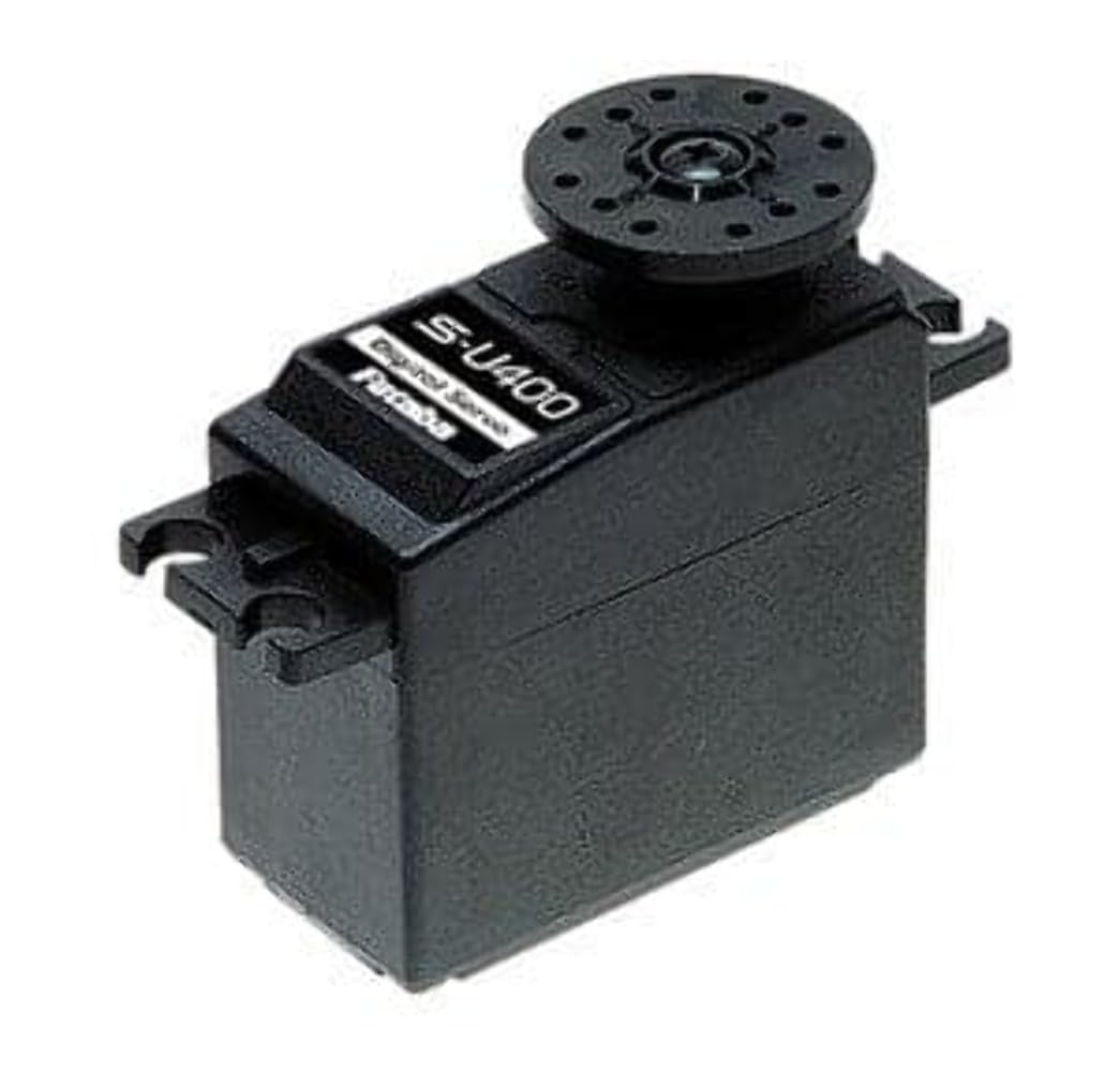
Image of the Futaba S-U400 Standard Servo, showing its compact design and wiring.
4. Specifications
| Feature | Description |
|---|---|
| Model | S-U400 (FUT011023333) |
| Type | Digital Standard Servo |
| Voltage Compatibility | High Voltage (HV) |
| S.Bus2 Compatibility | Yes |
| Gear Material | Plastic |
| Speed @ 6.6V | 0.14 sec/60 degrees |
| Speed @ 7.4V | 0.13 sec/60 degrees |
| Torque @ 6.6V | 98.6 oz/in |
| Torque @ 7.4V | 109.7 oz/in |
| Dimensions (LxWxH) | 40 x 20 x 36.1 mm (1.6 x 0.8 x 1.5 inches) |
| Weight | 1.38 oz |
| Spline | 6mm/25T |
| Motor Type | 3-Pole Cored |
5. Setup
5.1 Mounting the Servo
- Identify a suitable mounting location in your RC model that provides adequate clearance for servo movement and linkage.
- Use the provided mounting screws to secure the servo firmly to the servo mount. Avoid overtightening, which can crack the servo case.
- Attach the appropriate servo horn from the accessory pack to the servo output shaft. Ensure it is centered before securing it with the small screw.
5.2 Electrical Connection
- Connect the servo's three-wire cable to the corresponding channel on your receiver. The standard color code is typically: Brown (Ground), Red (Positive Voltage), Orange/Yellow/White (Signal).
- Ensure your power supply (battery/BEC) provides the correct high voltage (6.6V to 7.4V) for optimal servo performance.
- If using S.Bus2, connect the servo to an S.Bus2 port on your compatible receiver or S.Bus hub. Refer to your receiver's manual for specific S.Bus2 setup instructions.
6. Operating
Once the servo is correctly mounted and connected, power on your RC system (transmitter first, then receiver/model). The servo should initialize and move to its neutral position. Test the servo's movement by operating the corresponding control on your transmitter. Observe for smooth and consistent motion throughout its range.
- Centering: Ensure the servo horn is perfectly centered when the transmitter stick is at neutral. Adjust the trim settings on your transmitter if necessary.
- Travel Adjustment: Set the servo's travel limits (endpoints) on your transmitter to prevent over-travel, which can bind the linkage or damage the servo.
- Direction: If the servo moves in the opposite direction to your control input, reverse the servo direction on your transmitter.
7. Maintenance
- Regularly inspect the servo for any signs of physical damage, loose screws, or worn gears.
- Keep the servo clean and free from dirt, dust, and debris. Use a soft, dry brush or cloth for cleaning.
- Check servo linkages for smooth movement and ensure they are not binding, which can put undue strain on the servo.
- Avoid exposing the servo to extreme temperatures or direct sunlight for prolonged periods.
8. Troubleshooting
8.1 Servo Not Responding
- Check all electrical connections to ensure they are secure and correctly plugged into the receiver.
- Verify that the receiver and transmitter are powered on and properly bound.
- Confirm the battery has sufficient charge and is providing the correct voltage.
- Test the servo on a different receiver channel or with another known working servo to isolate the issue.
8.2 Erratic or Jerky Movement
- Inspect servo linkages for any binding or obstruction.
- Check for interference from other electronic components. Ensure proper spacing and shielding.
- Verify that the servo horn is securely attached and not slipping on the spline.
- Ensure the power supply is stable and not experiencing voltage drops under load.
8.3 Servo Making Noise
- A slight buzzing sound is normal for digital servos. However, excessive noise may indicate binding in the linkage or damaged gears.
- Check for any physical obstructions preventing smooth movement.
- If the noise is accompanied by poor performance, inspect the gears for wear or damage.
9. Warranty and Support
Futaba products are manufactured to high standards and undergo rigorous quality control. For warranty information, please refer to the official Futaba website or contact your local distributor. For technical support, please visit the Futaba support portal or consult your product retailer.
Note: Keep your purchase receipt as proof of purchase for warranty claims.


