
EPEVER XTRA4415N
EPEVER MPPT Solar Charge Controller XTRA4415N User Manual
Model: XTRA4415N
1. Product Overview
The EPEVER MPPT Solar Charge Controller XTRA4415N is an advanced Maximum Power Point Tracking (MPPT) controller designed for off-grid photovoltaic systems. It efficiently manages power flow from solar panels to batteries, ensuring optimal charging and extending battery lifespan. This controller supports various battery types and features a common negative grounding design, making it suitable for a wide range of applications.

Figure 1.1: EPEVER MPPT Solar Charge Controller XTRA4415N
This image shows the EPEVER MPPT Solar Charge Controller XTRA4415N from a slightly elevated, angled perspective, highlighting its compact design and the integrated LCD display and control buttons on the front panel. The heat sink fins are visible along the bottom edge.
2. Safety Instructions
Please read all instructions and warnings carefully before installation and operation. Failure to follow these instructions may result in electric shock, fire, or severe injury.
- Ensure all power sources are disconnected before installation or maintenance.
- Use appropriate personal protective equipment (PPE) during installation.
- The PV array can produce high voltages, even in low light conditions. Exercise extreme caution.
- Ensure proper ventilation around the controller to prevent overheating.
- Do not expose the controller to water or excessive humidity.
- Use only recommended wire gauges (#6AWG / 16mm2 recommended) and ensure all connections are tight.
- This device is for indoor use only.
3. Package Contents
Verify that all items are included in your package:
- 1 x EPEVER MPPT Solar Charge Controller 40A (Model: XTRA4415N-XDS2)
- 1 x Temperature Sensor Unit (Model: RT-MF58R47K3.81A)
- 1 x User Manual (English)
4. Features
The XTRA4415N controller incorporates several advanced features for efficient and reliable solar power management:
- Advanced MPPT Technology: High tracking efficiency up to 99.5% and peak conversion efficiency of 98% for maximizing energy harvest.
- High Power Capacity: Supports max. PV array power of 520W (12V), 1040W (24V), 1560W (36V), and 2080W (48V).
- Common Negative Grounding: Designed for versatile applications.
- Battery Compatibility: Supports lead-acid (Sealed, Gel, Flooded, User-defined) and lithium (LiFePO4, Li[NiCoMn]O2, User-defined) battery types.
- Four-Stage Charging: Bulk, Absorption, Float, and Equalization stages to optimize battery health and lifespan.
- Comprehensive Protections: Built-in against reverse polarity, overcharging, over-discharging, overload, short-circuiting, and reverse current.
- Real-Time Energy Statistics: Monitors energy flow for system optimization.
- User-Friendly Interface: Features three different color LED indicators and a large LCD display for intuitive status monitoring.
- Easy Control: Five buttons allow for simple parameter adjustment and browsing.
- Communication Port: RS485 interface for external accessories like MT50 remote meter, eBox adapter for APP monitoring, or PC software.
- IP33 Ingress Protection: Provides protection against solid objects larger than 2.5mm and water spray.
- High-Temp Power Derating: Automatically reduces power output to prevent damage from excessive heat.

Figure 4.1: Key Features of the XTRA4415N Controller
This diagram illustrates the main features of the EPEVER MPPT Solar Charge Controller, including High MPPT Efficiency, IP33 Ingress Protection, Real-Time Energy Statistics, Modbus Protocol & RS485, Optional LCD Display Units, High-Temp Power Derating, Power & Current Limitation, Multiple Load Modes, Supports Lead-Acid & Li-ion Battery, and High Charging Conversion Efficiency.
5. Setup and Installation
Proper installation is crucial for the safe and efficient operation of your solar charge controller. Follow these steps carefully:
5.1 Mounting the Controller
- Choose a well-ventilated, dry location away from direct sunlight and heat sources.
- Ensure there is sufficient space around the controller for air circulation, especially around the heatsink.
- Mount the controller vertically using the Φ5mm mounting holes.

Figure 5.1: Front View with Mounting Hole and Display Unit
This image provides a front view of the EPEVER MPPT Solar Charge Controller, clearly labeling the 'Mounting Hole', 'Display Unit', and 'Terminal Protection Cover'.
5.2 Wiring Connections
Important: Always connect in the specified order to prevent damage to the controller or system components. Disconnect in the reverse order.
- Connect the Battery: Connect the battery to the controller's battery terminals. Ensure correct polarity (+ to + and - to -). The controller will detect the system voltage automatically.
- Connect the Load: Connect the DC load to the controller's load terminals.
- Connect the PV Array: Connect the solar panels to the controller's PV terminals. Ensure correct polarity and that the PV open circuit voltage does not exceed the controller's maximum input voltage (150V).
Disconnection Order: To disconnect the system, follow the reverse order: 3. PV Array → 2. Load → 1. Battery.
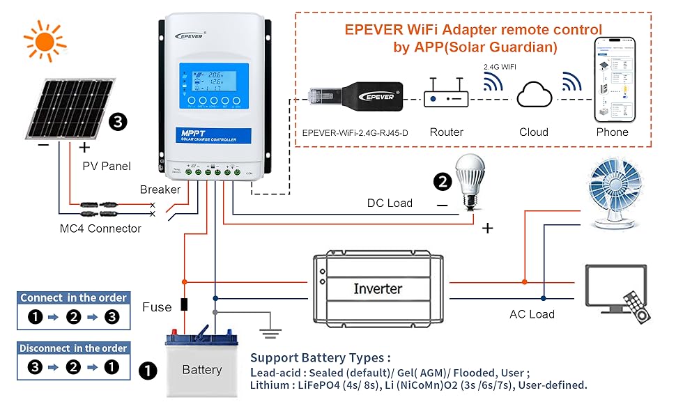
Figure 5.2: Typical Solar System Wiring Diagram
This diagram illustrates the correct wiring sequence for a solar power system using the EPEVER controller, showing connections for PV panels, battery, DC load, and an inverter for AC loads. It emphasizes the connection order (1. Battery, 2. Load, 3. PV Panel) and disconnection order (3. PV Panel, 2. Load, 1. Battery).

Figure 5.3: Controller Terminals Overview
This image provides a detailed view of the EPEVER MPPT Solar Charge Controller's connection points, clearly labeling the 'RS485 port (Communication port)', 'Load terminals', 'Battery terminals', 'PV terminals', 'RTS port', and 'Grounding terminal'.
5.3 Temperature Sensor Connection
Connect the included temperature sensor unit (RT-MF58R47K3.81A) to the RTS port on the controller. This allows the controller to compensate for battery charging voltage based on ambient temperature, improving charging accuracy and battery lifespan.
6. Operating the Controller
The XTRA4415N features an intuitive LCD display and five control buttons for easy operation and monitoring.
6.1 LCD Display and LED Indicators
The LCD displays various system parameters, while the LED indicators provide quick status updates:

Figure 6.1: LED Indicator Status and Instructions
This table details the meaning of the LED indicators on the EPEVER controller. It shows the color, status (e.g., Solid, Flashing), and corresponding instruction or condition for PV, Battery, and Load indicators, as well as combined PV&BATT LED states.
6.2 Button Functions
- PV/+ Button: Used to navigate forward through PV parameters or increase values during setting.
- BATT/- Button: Used to navigate backward through Battery parameters or decrease values during setting.
- LOAD/- Button: Used to navigate through Load parameters or decrease values during setting. Also controls load ON/OFF.
- SET Button: Enters/confirms parameter settings.
- /ESC Button: Exits setting mode or returns to the previous menu.
6.3 Battery Type Selection and Parameter Settings
The controller supports various battery types. For optimal performance and battery longevity, select the correct battery type or customize parameters for user-defined batteries.

Figure 6.2: Suitable Battery Types and Parameters
This comprehensive table outlines the default charging parameters for various battery types supported by the EPEVER controller, including Sealed, Gel, Flooded, User-defined, LiFePO4 (LFP4S, LFP8S, LFP16S), and Li(NiCoMn)O2 (LCNM3S, LCNM6S, LCNM7S, LCNM13S, LCNM14S). It lists values for Over Voltage Disconnect, Charging Limit, Over Voltage Reconnect, Boost Charging, Float Charging, Boost Reconnect, Low Voltage Reconnect, Under Voltage Warning, Low Voltage Disconnect, Discharging Limit, Equalize Duration, and Boost Duration.
For detailed customization of user-defined battery types or advanced monitoring, EPEVER accessories such as the MT50 remote meter, eBox adapter (for APP monitoring), eLOG01 logger, or PC software are required via the RS485 communication port.
7. Maintenance
Regular maintenance ensures the longevity and optimal performance of your solar charge controller.
- Check Connections: Periodically inspect all wiring connections for tightness and corrosion. Loose connections can cause overheating and poor performance.
- Clean the Controller: Keep the controller clean and free of dust and debris. Use a dry cloth to wipe the surface. Ensure the heatsink fins are clear for proper heat dissipation.
- Inspect Wiring: Check the insulation of all wires for any signs of damage or wear.
- Monitor Performance: Regularly check the LCD display for system parameters and ensure the controller is operating within expected ranges.
- Battery Inspection: Inspect battery terminals for corrosion and ensure batteries are properly maintained according to their manufacturer's guidelines.
8. Troubleshooting
If you encounter issues with your EPEVER MPPT Solar Charge Controller, refer to the following common problems and solutions:
| Problem | Possible Cause | Solution |
|---|---|---|
| No PV charging | PV array not connected, reversed polarity, insufficient sunlight, PV array voltage too low/high. | Check PV connections and polarity. Ensure adequate sunlight. Verify PV array voltage is within controller's operating range. |
| Battery not charging fully | Incorrect battery type setting, temperature sensor issue, battery aging. | Verify battery type setting. Check temperature sensor connection. Consider battery health. |
| Load not working | Load disconnected, overload, short circuit, battery low voltage disconnect. | Check load connections. Reduce load. Check for short circuits. Ensure battery voltage is above LVD. |
| Controller display off | No power from battery or PV. | Check battery and PV connections. Ensure battery voltage is above minimum operating voltage. |
| Error code on display | Specific system fault. | Refer to the LED Indicator table (Figure 6.1) for specific error meanings and corresponding actions. |
If the problem persists after attempting these solutions, please contact technical support.
9. Specifications
| Parameter | Value |
|---|---|
| Model | XTRA4415N-XDS2 |
| Rated Charge/Discharge Current | 40 Amp |
| Nominal System Voltage | 12V/24V/36V/48V DC Auto Work |
| Max. PV Input Power | 520W@12V, 1040W@24V, 1560W@36V, 2080W@48V |
| Max. PV Open Circuit Voltage | 150V (at min. operating temp), 138V (at 25℃) |
| Battery Voltage Range | 8~68V |
| MPP Voltage Range | V(BAT+2V)~108V |
| Grounding | Common Negative Grounding |
| RS485 Interface | 5VDC/200mA (RJ45) |
| Tracking Efficiency | ≥99.5% |
| Max. Conversion Efficiency | 98% |
| Working Environment Temperature | -25℃~+50℃ |
| Storage Temperature Range | -20°C -- +70°C / -4°F -- 158°F |
| LCD Backlight Time | 60S (Default) |
| Controller Terminals | #6AWG (16mm2) |
| Recommended Wire Cable | #6AWG (16mm2) |
| Mounting Hole Size | Φ5mm |
| Dimensions (L x W x H) | 255 x 189 x 83.2 mm (10.04 x 7.44 x 3.28 inches) |
| Weight | 2.47 KG (6.57 Pounds) |
10. Warranty and Support
For technical support, warranty inquiries, or any questions regarding your EPEVER MPPT Solar Charge Controller, please contact the officially authorized vendor, Goland Century. They can provide assistance with product operation, troubleshooting, and any service-related needs.
Contact information for Goland Century can typically be found on your purchase receipt or the product packaging.
Related documentsXTRA4415N


Ask a question about this manual
Ask about setup, troubleshooting, compatibility, parts, safety, or missing instructions. Manuals+ will review the question and use this page’s manual context to help answer it.