
1. Introduction
This manual provides detailed instructions for the ATNSINC NRF24L01+PA+LNA RF Wireless Transceiver Module. This 2.4GHz ISM band transceiver is designed for various wireless communication applications, offering extended range with its power amplifier and SMA antenna. It is compatible with platforms like Raspberry Pi and includes a breakout adapter for convenient integration.
2. Product Overview
2.1 Key Features
- 2.4GHz ISM band transceiver with power amplifier (PA) and low noise amplifier (LNA).
- Compatible with Raspberry Pi and other microcontrollers via 4-pin Serial Peripheral Interface (SPI).
- Extended effective communication distance due to PA and SMA antenna.
- Supports auto-acknowledge and auto-retransmit abilities.
- Capable of supporting up to six channels of data reception.
- Configurable parameters: 125 selectable frequency channels, output power, and data rates (250kbps, 1Mbps, 2Mbps).
- Breakout adapter with on-board 3.3V voltage regulator, accepting 5V input.
2.2 Package Contents
- 2 x NRF24L01+PA+LNA Wireless Transceiver Module
- 2 x SMA Antenna
- 2 x NRF24L01+ Breakout Adapter
2.3 Component Identification

Figure 1: Front and back view of the NRF24L01+PA+LNA Wireless Transceiver Module, showing the main chip, antenna connector, and pin headers.

Figure 2: Front and back view of the NRF24L01+ Breakout Adapter, illustrating the pin headers for the module and the external connections.
3. Specifications
| Feature | Value |
|---|---|
| Operating Frequency | 2.4GHz ISM Band |
| Communication Interface | 4-pin Serial Peripheral Interface (SPI) |
| Data Rates | 250kbps, 1Mbps, 2Mbps |
| Channels | 125 selectable channels |
| Antenna Type | SMA Antenna |
| Breakout Adapter Input Voltage | +5V |
| Module Operating Voltage | 3.3V (regulated by breakout adapter) |
| Module Dimensions (approx.) | 41mm x 15mm (1.61in x 0.59in) |
| Breakout Adapter Dimensions (approx.) | 26mm x 19mm (1.02in x 0.74in) |
| Antenna Length (approx.) | 107mm (4.21in) |
| Item Weight | 0.704 ounces (total package) |

Figure 3: Approximate dimensions of the NRF24L01+PA+LNA module, breakout adapter, and SMA antenna.
4. Setup Instructions
Follow these steps to set up your NRF24L01+PA+LNA Wireless Transceiver Module:
- Connect the Transceiver Module to the Breakout Adapter: Carefully align the pins of the NRF24L01+PA+LNA module with the corresponding headers on the breakout adapter. Ensure all pins are correctly seated. The breakout adapter provides the necessary 3.3V power to the module from a 5V input.
- Attach the SMA Antenna: Screw the SMA antenna onto the connector on the NRF24L01+PA+LNA module. Ensure it is finger-tight to establish a secure connection.
- Connect to a Microcontroller: The breakout adapter provides pins for VCC, GND, and the 4-pin SPI interface (CSN, SCK, MOSI, MISO, CE, IRQ). Connect these pins to your microcontroller (e.g., Raspberry Pi, Arduino) according to its documentation. The breakout adapter's VCC pin should be connected to a +5V power supply from your microcontroller or an external source, and GND to ground.
- Software Configuration: Install the necessary libraries for NRF24L01+ communication on your microcontroller. Configure the SPI interface and initialize the module.
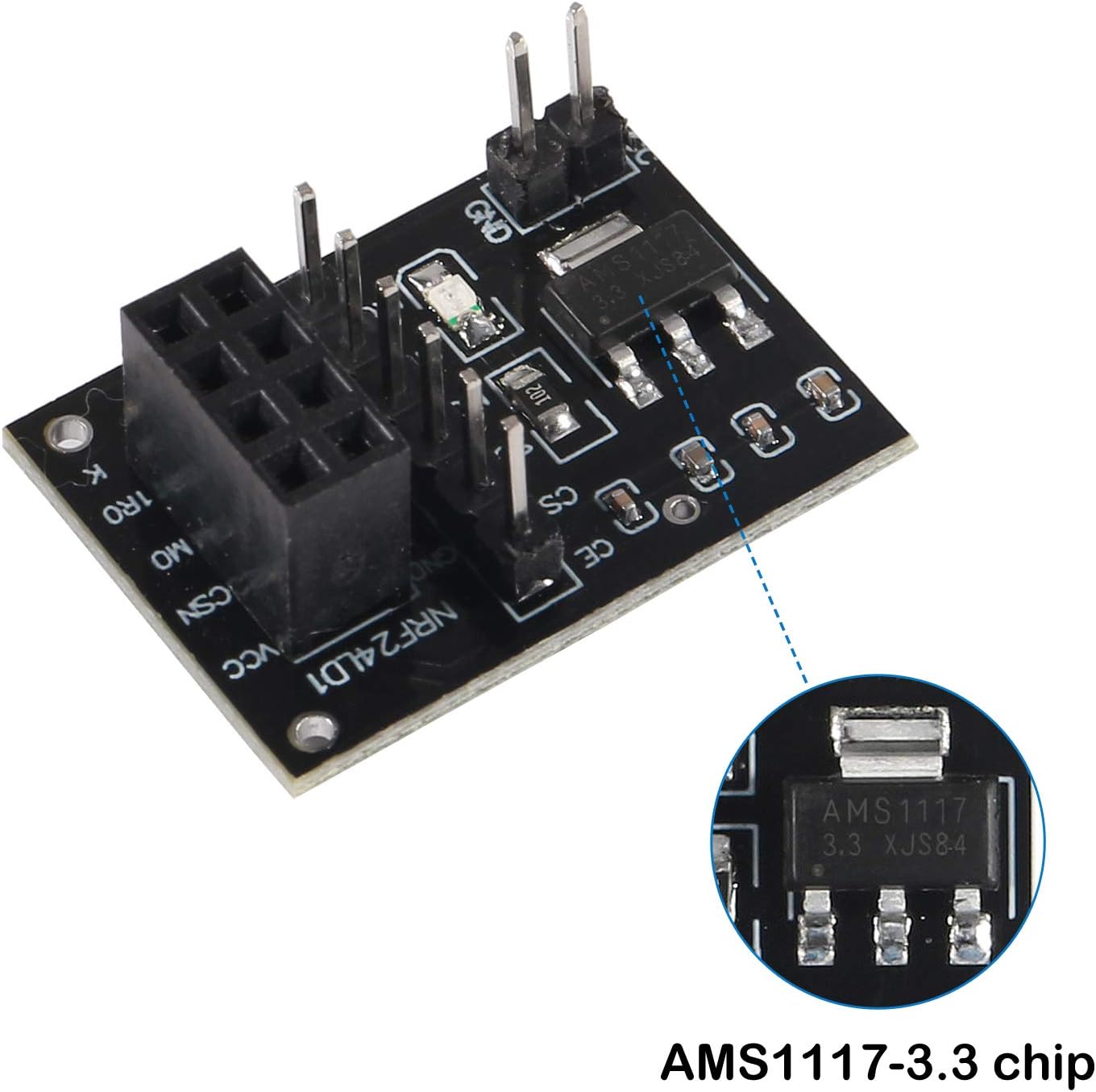
Figure 4: The AMS1117-3.3 voltage regulator on the breakout adapter, which converts 5V input to 3.3V for the transceiver module.

Figure 5: Illustration of how to connect the SMA antenna to the NRF24L01+PA+LNA module.

Figure 6: Example circuit diagram and pinout for connecting the NRF24L01+PA+LNA module. Refer to this for wiring guidance.
Note: For visual guidance on wiring, you may refer to external resources such as YouTube videos. A common search term would be "NRF24L01+ wiring tutorial".
5. Operating Instructions
Once the module is physically connected and software libraries are installed, you can begin operating the transceiver:
- Initialize the Module: Use your chosen library to initialize the NRF24L01+ module. This typically involves setting up the SPI communication and performing a basic check to ensure the module is detected.
- Configure Parameters:
- Frequency Channel: Select one of the 125 available channels (e.g., 2.400 GHz to 2.525 GHz). Both transmitting and receiving modules must be set to the same channel.
- Output Power: Adjust the transmitting power level. Higher power can increase range but consumes more energy.
- Data Rate: Choose between 250kbps, 1Mbps, or 2Mbps. All communicating modules must use the same data rate.
- Set Up Communication Pipes: The NRF24L01+ supports up to six data pipes for reception. Configure unique addresses for each pipe. For basic communication, set up one transmitting address and one receiving address.
- Transmit Data: Load the data you wish to send into the module's transmit buffer and initiate transmission. The module handles auto-acknowledgment and retransmission if enabled.
- Receive Data: Continuously check for incoming data on the configured receive pipes. When data is available, read it from the module's receive buffer.
5.1 Typical Applications
The NRF24L01+PA+LNA module is suitable for a wide range of wireless applications, including:
- Wireless remote control (e.g., RC planes/vehicles)
- Wireless audio and voice transmission (e.g., VoIP)
- Wireless sensor networks
- Smart home automation
- Somatosensory devices
- RFID and NFC applications
6. Troubleshooting
If you encounter issues with your NRF24L01+PA+LNA module, consider the following troubleshooting steps:
- Module Not Responding/Not Detected:
- Verify all wiring connections, especially SPI pins (CSN, SCK, MOSI, MISO, CE, IRQ), VCC, and GND. Incorrect wiring is a common cause of issues.
- Ensure the breakout adapter is receiving a stable +5V input and the module is receiving a stable 3.3V. Check for proper power supply.
- Confirm that your microcontroller's SPI interface is correctly configured and enabled.
- Test with a known working example code or library to rule out software issues.
- Intermittent Communication/Poor Range:
- Ensure the SMA antenna is securely attached to the module.
- Check for environmental interference. Other 2.4GHz devices (Wi-Fi, Bluetooth) can affect performance. Try changing the operating frequency channel.
- Increase the output power setting in your software configuration, if applicable.
- Ensure both modules are configured with the same data rate and frequency channel.
- Physical obstructions (walls, metal objects) can significantly reduce range. Test in an open environment.
- Data Corruption:
- Verify that the data rates are matched between sender and receiver.
- Check for proper SPI communication timing and data integrity in your code.
- Ensure power supply is stable and free from noise.
7. Maintenance
The NRF24L01+PA+LNA module requires minimal maintenance:
- Keep the module and antenna clean and free from dust and moisture.
- Avoid exposing the module to extreme temperatures or direct sunlight.
- Ensure all connections remain secure, especially the antenna and pin headers.
- Handle the module with care to prevent damage to components or pins.
8. Warranty and Support
Specific warranty information for this product is not provided in the available data. For warranty details, technical support, or further assistance, please contact the manufacturer, ATNSINC, directly through their official channels or the retailer from whom the product was purchased.