
1. Introduction
1.1 Product Overview
The Graigar TENMARS TM-903 Multimedia Cable Tester is a portable instrument designed for verifying and troubleshooting various cable types. It provides comprehensive testing capabilities for twisted pair LAN cables (UTP, STP), video coaxial cables, and RJ11 voice cables. The device displays detailed wire-map information, including opens, shorts, miswires, and split pairs, along with remote ID numbers on a single screen. It also features cable length measurement.
1.2 Key Features
- Detects opens, shorts, miswires, and split pairs on twisted pair cabling.
- Measures cable length up to 255 meters (836 feet).
- Supports multiple remote IDs (up to 8) for RJ-45, F-Connector, and RJ11 cables.
- Features a low battery detector.
- Includes auto backlit display for improved visibility.
- Equipped with an auto power-off function to conserve battery life.
2. Safety Information
Please read and understand all safety instructions before operating the TENMARS TM-903. Failure to follow these instructions may result in injury or damage to the device.
- Do not attempt to repair or modify the device. Refer all servicing to qualified personnel.
- Ensure correct battery polarity when installing batteries.
- Remove batteries if the device will not be used for an extended period to prevent leakage.
- Avoid exposing the device to extreme temperatures, humidity, or direct sunlight.
- Do not use the device near water or in damp environments.
- Always disconnect cables from active networks or power sources before testing.
3. Components and Controls
3.1 Main Unit Overview
The main unit features an LCD display, control buttons, and various ports for cable connections.

Figure 1: Front view of the TM-903 tester. The LCD displays test results, and the yellow buttons below control navigation and power. The 'L/W/S' button selects test modes, and 'SET/UNIT' adjusts settings or units.
3.2 Rear Panel and Battery Compartment
The rear panel houses the battery compartment and a helpful wiring diagram for quick reference.

Figure 2: Rear view of the TM-903, illustrating the battery compartment cover and a printed wiring diagram for standard RJ-45 pinouts.
3.3 Connection Ports
The top of the main unit features dedicated ports for different cable types.

Figure 3: Top view of the TM-903, highlighting the RJ-45 (LAN), F-Connector (coaxial), and RJ-11 (voice) ports for connecting cables.
3.4 Included Accessories
The TM-903 comes with essential accessories for immediate use.

Figure 4: The TM-903 tester with its remote ID unit (labeled '1'), a black carrying case, and various test cables (RJ-45 to RJ-45, F-connector, and RJ-11).
4. Setup
4.1 Battery Installation
The TM-903 requires six 1.5V AAA batteries for operation.
- Locate the battery compartment on the rear of the main unit (refer to Figure 2).
- Slide the battery compartment cover downwards to open it.
- Insert six 1.5V AAA batteries, ensuring correct polarity as indicated inside the compartment.
- Replace the battery compartment cover, sliding it upwards until it clicks securely into place.
4.2 Connecting Cables for Testing
Proper connection is crucial for accurate test results.
- For LAN (RJ-45) Cables: Connect one end of the RJ-45 cable to the RJ-45 port on the main unit and the other end to the RJ-45 port on the remote ID unit.
- For Coaxial (F-Connector) Cables: Connect one end of the coaxial cable to the F-Connector port on the main unit and the other end to the F-Connector port on the remote ID unit.
- For Voice (RJ-11) Cables: Connect one end of the RJ-11 cable to the RJ-11 port on the main unit and the other end to the RJ-11 port on the remote ID unit.
- Ensure all connections are secure before initiating a test.
5. Operation
5.1 Powering On/Off
- To power on the device, press and hold the central yellow power button (labeled with a circle and vertical line) until the display illuminates.
- To power off the device, press and hold the central yellow power button again until the display turns off. The device also features an auto power-off function after a period of inactivity.
5.2 Wire-Map Test
The wire-map test identifies the continuity and correct pairing of wires within a cable.
- Connect the cable to be tested to the main unit and the remote ID unit as described in Section 4.2.
- Power on the device.
- Press the 'L/W/S' button to cycle through test modes until 'WIREMAP' is displayed on the screen (refer to Figure 1).
- Press the 'TEST' button (located below 'L/W/S') to initiate the wire-map test.
- The LCD will display the wire-map results, indicating any opens, shorts, miswires, or split pairs. The remote ID number will also be shown.
5.3 Length Measurement
The TM-903 can measure the length of connected cables.
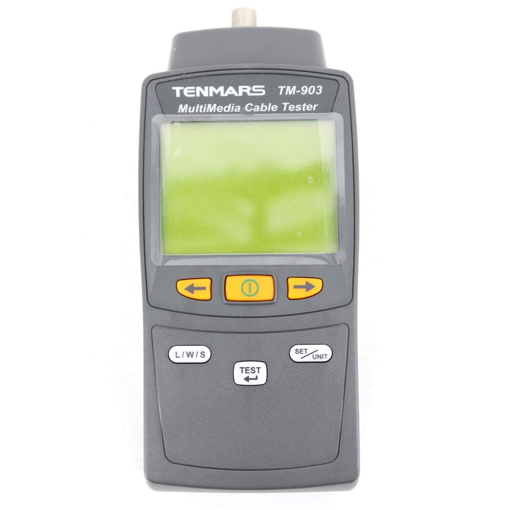
Figure 5: The TM-903 display showing 'LENGTH' mode with a measurement of '0.0 m'.
- Connect the cable to be tested to the main unit and the remote ID unit.
- Power on the device.
- Press the 'L/W/S' button to cycle through test modes until 'LENGTH' is displayed on the screen (refer to Figure 5).
- Press the 'TEST' button to initiate the length measurement.
- The LCD will display the cable length in the selected unit (meters or feet).
5.4 Changing Length Units
To switch between meters and feet for length measurements:
- While in 'LENGTH' mode, press the 'SET/UNIT' button. The unit displayed on the screen will toggle between 'm' (meters) and 'ft' (feet).
5.5 Using Multiple Remote IDs
The TM-903 supports up to 8 remote ID units for testing multiple cable runs simultaneously or identifying specific cables.
- Connect the main unit to one end of a cable and a numbered remote ID unit (e.g., Remote ID 1, 2, etc.) to the other end.
- Perform a wire-map or length test. The display will show the corresponding remote ID number, allowing you to identify which cable is being tested.
6. Maintenance
Proper maintenance ensures the longevity and accuracy of your TM-903.
- Cleaning: Use a soft, dry cloth to clean the device. Do not use abrasive cleaners or solvents.
- Storage: Store the device in a cool, dry place, away from direct sunlight and extreme temperatures. Use the provided carrying case for protection during storage and transport (refer to Figure 4).
- Battery Replacement: Replace batteries when the low battery indicator appears on the display to ensure accurate measurements. Refer to Section 4.1 for battery installation instructions.
7. Troubleshooting
If you encounter issues with your TM-903, refer to the following common problems and solutions:
- Device does not power on:
- Check if batteries are installed correctly with proper polarity.
- Replace old or depleted batteries with new ones.
- Ensure the power button is pressed and held sufficiently.
- No display or dim display:
- Check battery level; replace if low.
- Ensure the device is not exposed to extreme cold, which can affect LCD performance.
- Inaccurate wire-map or length readings:
- Ensure cables are securely connected to both the main unit and the remote ID.
- Verify that the cable itself is not damaged or faulty.
- Confirm that the correct cable type is being tested (e.g., RJ-45 for LAN).
- Check for interference from nearby electrical equipment.
- Remote ID not detected:
- Ensure the remote ID unit is properly connected to the cable.
- Verify the cable connecting the main unit and remote ID is functional.
8. Specifications
| Parameter | Specification |
|---|---|
| Connectors Type | RJ-45, F-Connector, and RJ11 |
| Cable Category | LAN cable (UTP, STP), video coaxial cable, and voice cable |
| Wire-map Test | Detects opens, shorts, miswires, split pairs |
| Length Test Range | Up to 255 M (836 ft) |
| Length Resolution | 0.1 m (ft) |
| Length Units | Meter and Foot |
| Length Accuracy | +/- 10% + 1.0M (3 ft) |
| Power | 1.5V battery x 6 (AAA) |
| Battery Life | Approx. 200 continuous tests |
| Operating Maximum Power | 20mA |
| Operating Temperature and RH | 5 to 40 °C, below 80% RH |
| Storage Temperature and RH | -10 to 60 °C, below 70% RH |
| Dimensions | 156(L) x 73(W) x 35(H) mm |
| Weight | About 170g |
| Item Model Number | TM-903 |
| UPC | 761272052707 |
9. Warranty and Support
For warranty information or technical support, please refer to the documentation provided with your purchase or contact Graigar customer service. Keep your purchase receipt as proof of purchase for warranty claims.