
AZZA CSAZ-340F
AZZA CSAZ-340F CELESTA ATX Mid Tower Gaming Case
User Manual
1. Introduction
This manual provides comprehensive instructions for the installation, operation, and maintenance of your AZZA CSAZ-340F CELESTA ATX Mid Tower Gaming Case. Please read this manual thoroughly before beginning installation to ensure proper setup and to maximize the performance and longevity of your system components.

Figure 1: The AZZA CSAZ-340F CELESTA Mid Tower ATX Case, showcasing its design and form factor.
2. Safety Information
- Always disconnect the power supply from the wall outlet before installing or removing any components inside the case.
- Handle all components with care to prevent damage from electrostatic discharge (ESD). Consider using an anti-static wrist strap.
- Keep the case and components away from liquids and excessive moisture.
- Ensure proper ventilation around the case to prevent overheating.
- Do not attempt to modify the case structure or components, as this may void your warranty and pose safety risks.
- Keep small parts and packaging materials out of reach of children.
3. Package Contents
Verify that all items listed below are present in your package:
- AZZA CSAZ-340F CELESTA ATX Mid Tower Gaming Case
- Accessory Box (containing screws, standoffs, cable ties, etc.)
- User Manual (this document)
4. Specifications
The following table details the technical specifications of the AZZA CSAZ-340F CELESTA case:
| Feature | Specification |
|---|---|
| Brand | AZZA |
| Model Name | CSAZ-340F CELESTA |
| Case Type | Mid Tower |
| Motherboard Compatibility | ATX, Micro-ATX, Mini-ITX |
| Color | Black |
| Material | Metal |
| Power Supply Mounting Type | Bottom Mount |
| Cooling Method | Air |
| Fan Size (Included/Supported) | 120mm (Rear included), Supports 120mm/140mm |
| Max GPU Length | 320mm |
| Max CPU Cooler Height | 165mm |
| Max PSU Length | 160mm |
| 3.5" HDD Support | 2 |
| 2.5" SSD Support | 4/6 (depending on configuration) |
| Front Fan Support | 3 x 120mm or 3 x 140mm |
| Top Fan Support | 2 x 120mm or 2 x 140mm |
| Rear Fan Support | 1 x 120mm |
| Front Radiator Support | Up to 280mm/360mm |
| Top Radiator Support | 2 x 120mm (from image) |
| Rear Radiator Support | 1 x 120mm (from image) |
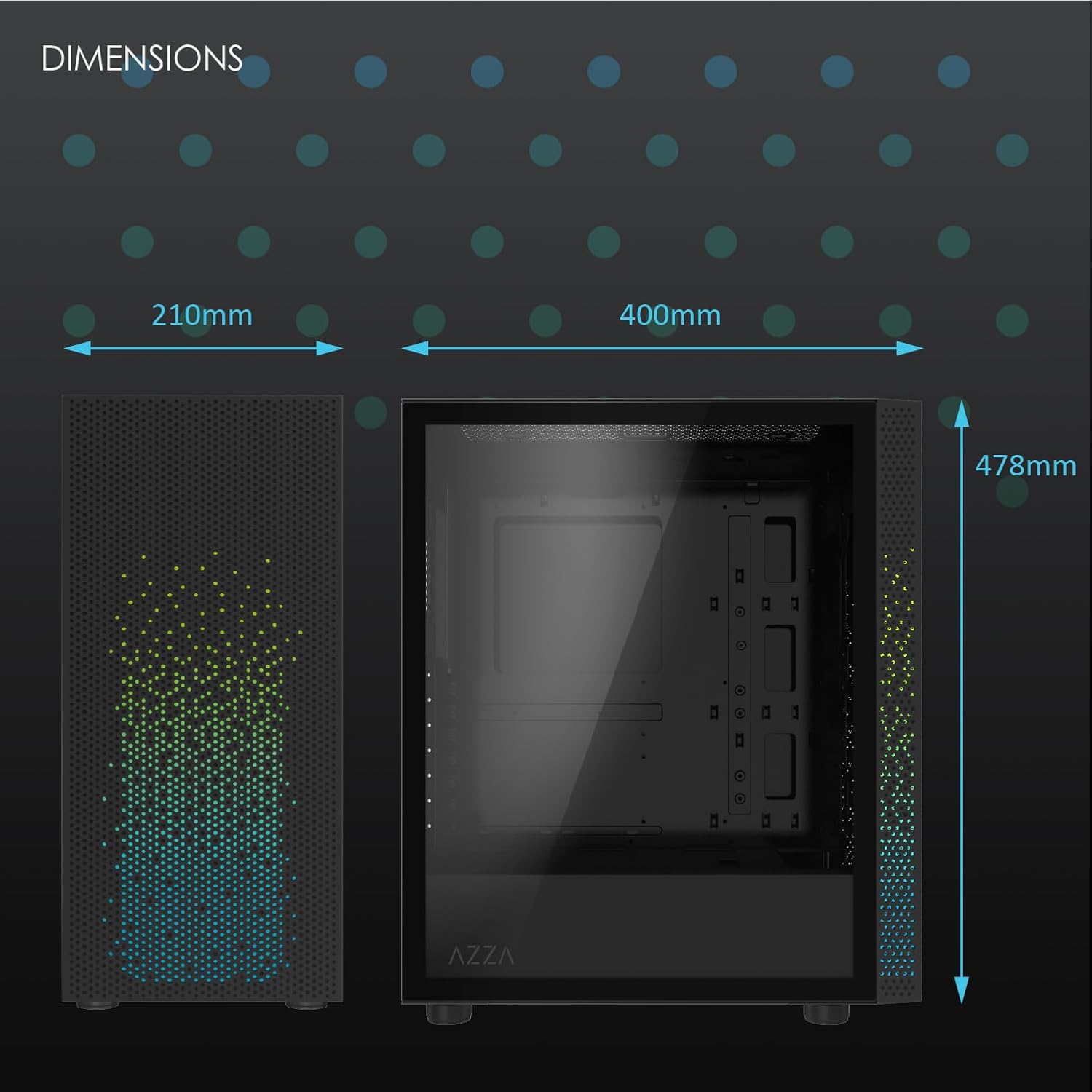
Figure 2: Physical dimensions of the AZZA CSAZ-340F CELESTA case: 210mm (width), 400mm (depth), 478mm (height).

Figure 3: Diagram illustrating fan and radiator mounting options for the AZZA CSAZ-340F CELESTA case, including front, top, and rear configurations.

Figure 4: Internal component support diagram for the AZZA CSAZ-340F CELESTA, showing maximum dimensions for CPU cooler, GPU, and PSU, along with drive bay locations.
5. Setup and Installation
Follow these steps to install your components into the AZZA CSAZ-340F CELESTA case.
5.1 Preparing the Case
- Place the case on a flat, stable surface.
- Remove the side panels. Typically, these are secured with thumbscrews at the rear of the case.
5.2 Motherboard Installation
- Install the I/O shield (if not pre-installed) into the rear opening of the case.
- Ensure the correct standoffs are installed for your ATX, Micro-ATX, or Mini-ITX motherboard. Adjust or add standoffs as needed using the provided tools.
- Carefully place your motherboard onto the standoffs, aligning the screw holes.
- Secure the motherboard with the appropriate screws from the accessory box. Do not overtighten.
5.3 Power Supply Unit (PSU) Installation
- Position the PSU in the bottom rear compartment of the case, ensuring the fan faces downwards (if there's a filtered vent) or upwards.
- Secure the PSU to the case with the provided screws from the rear.
- Route the necessary power cables through the cable management cutouts.
5.4 Storage Drive Installation (HDD/SSD)
- 3.5" HDDs: Locate the drive cage. Slide the 3.5" HDDs into the drive trays and secure them, often tool-less or with screws.
- 2.5" SSDs: Mount 2.5" SSDs to the dedicated mounting points on the motherboard tray or drive cage using screws.
- Connect SATA data and power cables to the installed drives.
5.5 Graphics Card (GPU) Installation
- Remove the necessary PCIe slot covers from the rear of the case.
- Carefully insert your graphics card into the appropriate PCIe slot on the motherboard until it clicks into place.
- Secure the graphics card to the case with screws.
- Connect any required PCIe power cables from the PSU to the graphics card.
5.6 CPU Cooler Installation
Install your CPU cooler according to its specific manufacturer instructions. Ensure it does not exceed the maximum height of 165mm.
5.7 Fan and Radiator Installation
The case supports various fan and radiator configurations:
- Front: Up to 3 x 120mm or 3 x 140mm fans, or radiators up to 280mm/360mm.
- Top: Up to 2 x 120mm or 2 x 140mm fans, or 2 x 120mm radiators.
- Rear: 1 x 120mm fan (pre-installed) or 1 x 120mm radiator.
Mount fans and radiators using the appropriate screws and ensure proper airflow direction.
5.8 Cable Management
Utilize the cable management cutouts and tie-down points behind the motherboard tray to route and secure cables. This improves airflow and aesthetics.
5.9 Final Assembly
- Double-check all connections and ensure no cables are obstructing fans.
- Reattach the side panels.
- Connect external peripherals (monitor, keyboard, mouse, etc.) and the power cable.
6. Operating Your System
Once all components are installed and connected, you can power on your system. The front panel features power and reset buttons, along with USB and audio ports for convenient access.

Figure 5: Close-up of the AZZA CSAZ-340F CELESTA's front panel, highlighting the integrated lighting effects.
7. Maintenance
- Dust Filters: Regularly clean the dust filters (if present) to maintain optimal airflow and cooling performance.
- Interior Cleaning: Periodically open the case and use compressed air to remove dust from components and fans. Ensure the system is powered off and unplugged before cleaning.
- Exterior Cleaning: Wipe the exterior surfaces with a soft, damp cloth. Avoid harsh chemicals.
8. Troubleshooting
If you encounter issues, consider the following common troubleshooting steps:
- System Not Powering On:
- Ensure the power cable is securely connected to both the PSU and the wall outlet.
- Check that the PSU switch is in the "ON" position.
- Verify all internal power connections (24-pin ATX, 8-pin CPU, PCIe power) are seated correctly.
- Confirm front panel power button cables are correctly connected to the motherboard.
- No Display Output:
- Ensure your monitor is connected to the graphics card (not the motherboard's integrated graphics ports, unless you are using integrated graphics).
- Reseat the graphics card in its PCIe slot.
- Check monitor input selection.
- Overheating:
- Verify all case fans are spinning and oriented correctly for airflow.
- Clean any dust filters and internal components.
- Ensure CPU cooler is properly seated and making good contact with the CPU.
9. Warranty and Support
For warranty information and technical support, please refer to the official AZZA website or contact AZZA customer service directly. Keep your proof of purchase for warranty claims.
AZZA Official Website: www.azza.com
Related documentsCSAZ-340F


Ask a question about this manual
Ask about setup, troubleshooting, compatibility, parts, safety, or missing instructions. Manuals+ will review the question and use this page’s manual context to help answer it.