1. Introduction
The EPEVER Tracer-BN Series MPPT solar charge controller is designed for solar power systems, featuring advanced Maximum Power Point Tracking (MPPT) technology. This manual provides essential instructions for the Tracer3215BN model, ensuring efficient and safe operation of your solar charging system. It is suitable for 12V/24V battery systems and supports a maximum PV input voltage of 150V.

Image: Front view of the EPEVER MPPT Charge Controller Tracer3215BN.
2. Safety Instructions
Observe the following safety guidelines during installation and operation to prevent damage to the controller or injury:
- Ensure proper wiring polarity for all connections (PV, battery, load).
- Do not exceed the maximum PV input voltage of 150VDC.
- Connect the battery first before connecting solar panels or loads.
- The controller features multiple electronic protections, including:
- PV short circuit protection
- PV overvoltage alarm protection
- PV current limiting protection
- PV reverse polarity protection
- Battery overcharge protection
- Battery over discharge protection
- Battery reverse polarity protection
- Load overload protection
- Load short circuit protection
- Overheating protection
- Install the controller in a well-ventilated area to ensure adequate heat dissipation.
- Avoid exposing the controller to direct sunlight, moisture, or corrosive environments.
3. Product Features
The Tracer3215BN controller incorporates advanced features for optimal solar system performance:
- Advanced MPPT Technology: High tracking efficiency (≥ 99.5%) and peak conversion efficiency (98%).
- Fast Tracking: Ultra-fast tracking speed and accurate Maximum Power Point (MPP) recognition.
- Wide MPP Operating Voltage Range: Adapts to various solar panel configurations.
- PV Current Limiting: Reliable automatic PV current limiting function.
- Durable Design: Die-cast aluminum housing for excellent heat dissipation and extended lifespan.
- Battery Compatibility: Supports Sealed, Gel, Flooded, and User-defined battery types. Includes battery temperature compensation.
- Flexible Load Control: Multiple load working modes: Manual Control, Light ON/OFF, Light On+Timer, and Time Control.
- Data Monitoring: Real-time energy statistics and data monitoring.
- Communication: RS485 port with industrial standard MODBUS open architecture for communication with MT50, APP, or PC software.
- Firmware Upgrade: Supports firmware upgrades for future enhancements.

Image: Visual summary of the Tracer-BN series features.
4. Components and Ports Identification
Familiarize yourself with the controller's external components and connection ports:
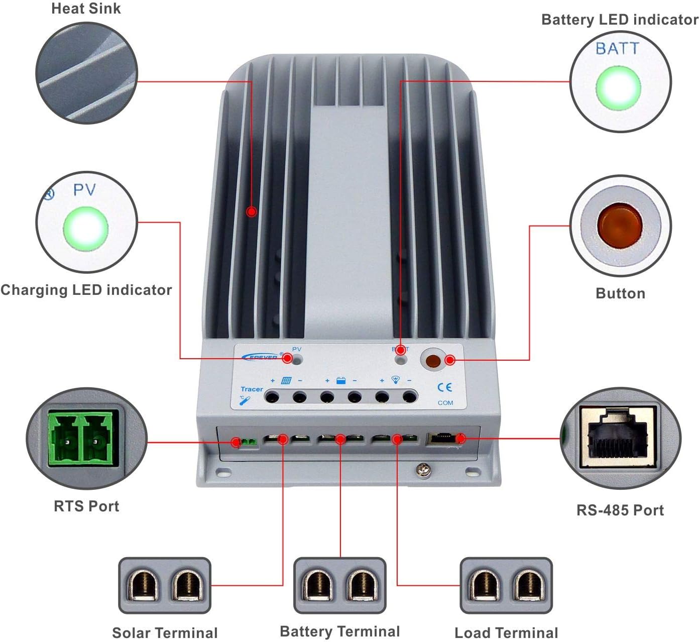
Image: Labeled diagram of the controller's external features.
| Item | Name | Item | Name |
|---|---|---|---|
| 1 | Heat Sink | 6 | Load Terminal |
| 2 | Charging LED indicator | 7 | RS-485 Port |
| 3 | RTS Port | 8 | Button |
| 4 | Solar Terminal | 9 | Battery LED indicator |
| 5 | Battery Terminal |
Explanation:
- RTS Port (3): Connection for a Remote Temperature Sensor to remotely detect battery temperature.
- RS-485 Port (7): Used to monitor the controller via PC and update controller software using an RS485 (RJ45 Interface) connection.
5. Setup and Installation
Follow these steps for proper installation of your Tracer3215BN controller:
- Mounting: Mount the controller vertically on a flat surface in a well-ventilated indoor area, away from direct sunlight, high temperatures, and moisture. Ensure sufficient space around the heat sink for air circulation. The mounting dimensions are 130mm x 204mm with Φ4.7 mounting holes.
- Wiring Order: Connect the system components in the following sequence to ensure safety and proper operation:
- Step 1: Connect the Battery: Connect the battery to the controller's battery terminals. Ensure correct polarity. The controller will detect the system voltage (12V/24V auto work).
- Step 2: Connect the Solar Panel: Connect the solar panel array to the controller's solar terminals. Ensure correct polarity.
- Step 3: Connect the Load: Connect the DC load to the controller's load terminals. Ensure correct polarity.
- Cable Sizing: Use appropriate cable sizes. For the Tracer3215BN, a power cable size of 6AWG (16mm²) is recommended.
- Grounding: The controller features common negative grounding. Ensure proper grounding according to local electrical codes.
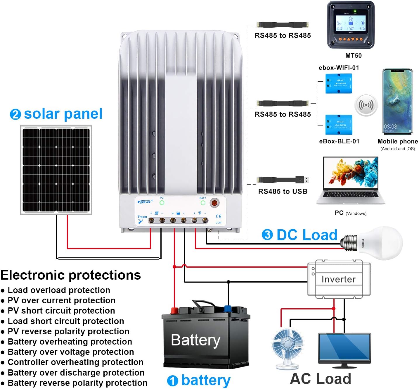
Image: Wiring diagram illustrating connections for battery, solar panel, and DC load.

Image: Controller dimensions for mounting reference.
6. Operating Instructions
Once installed, the controller operates automatically. However, you can configure settings and monitor performance:
- Battery Type Selection: The controller supports Sealed, Gel, Flooded, and User-defined battery types. Select the appropriate type through the controller's interface (if available) or via external monitoring tools (MT50, APP, PC software) to ensure correct charging parameters.
- Load Working Modes: Configure the DC load output behavior using the available modes:
- Manual Control: Turn the load ON/OFF manually.
- Light ON/OFF: Load turns ON at dusk and OFF at dawn.
- Light On+Timer: Load turns ON at dusk and stays ON for a set duration.
- Time Control: Load operates during specified time periods.
- Monitoring and Configuration: Use the optional MT50 remote meter, mobile application, or PC software connected via the RS485 port to monitor real-time data, view energy statistics, and adjust parameters.
7. Maintenance
Regular maintenance ensures the longevity and optimal performance of your charge controller:
- Inspect Connections: Periodically check all wiring connections (PV, battery, load) for tightness and corrosion. Loose connections can cause overheating and damage.
- Clean Controller: Keep the controller's exterior clean and free from dust and debris. Ensure the heat sink fins are clear for effective cooling.
- Ventilation: Verify that the installation area remains well-ventilated and free from obstructions that could impede airflow around the controller.
- Monitor Performance: Regularly check the controller's display or monitoring software for any error codes or unusual readings.
- Battery Health: Ensure your battery bank is properly maintained according to the battery manufacturer's guidelines.
8. Troubleshooting
If you encounter issues with your Tracer3215BN controller, consider the following:
- No Charging:
- Check PV panel connections and ensure correct polarity.
- Verify PV input voltage is within the controller's operating range (Max 150VDC).
- Ensure sufficient sunlight on the solar panels.
- Load Not Working:
- Check load connections and ensure correct polarity.
- Verify battery voltage is above the low voltage disconnect threshold.
- Check the selected load working mode.
- Ensure the load current does not exceed the rated discharge current (30A).
- Controller Overheating:
- Ensure adequate ventilation around the controller.
- Reduce the load or PV input if consistently operating at maximum capacity in high ambient temperatures.
- Error Codes: Refer to the controller's display or monitoring software for specific error codes and consult the EPEVER official documentation for their meaning and resolution.
9. Technical Specifications
Key technical data for the Tracer3215BN MPPT Charge Controller:

Image: Detailed technical specifications table.
| Parameter | Value |
|---|---|
| Nominal System Voltage | 12VDC / 24VDC Auto work |
| Rated Charge Current | 30A |
| Rated Discharge Current | 30A |
| Max. Solar Input Voltage | 150VDC |
| Max. PV Input Power (12V Battery) | 390W |
| Max. PV Input Power (24V Battery) | 780W |
| Self-consumption (12V) | ≤60mA |
| Self-consumption (24V) | ≤30mA |
| Mounting Dimension | 130mm x 204mm |
| Mounting Hole Size | Φ4.7 |
| Power Cable | 6AWG (16mm²) |
| Dimension | 281mm x 160mm x 60mm |
| Weight | 2.3kg |
| Working Environment Temperature | -35℃ ~ +55℃ |
| Relative Humidity | ≤95% (N.C.) |
| Enclosure | IP30 |
| Grounding | Common Negative |
| Communication Port | RS485 / RJ45 Interface |
10. Warranty Information
For detailed warranty terms and conditions, please refer to the product packaging, the official EPEVER website, or contact your authorized dealer. Warranty coverage typically includes defects in materials and workmanship under normal use.
11. Support
Should you require technical assistance, have questions regarding installation, operation, or troubleshooting, please contact:
- EPEVER Customer Service: Refer to the official EPEVER website for contact details.
- Authorized Sales Agent: GolandCentury (as mentioned in product information).
When contacting support, please have your product model (Tracer3215BN) and any relevant error codes or observations ready.


