
1. Introduction
This manual provides comprehensive instructions for the installation, operation, and maintenance of your Intellitronix LED Digital Replacement Gauge Panel. This product is specifically designed for 1992-1995 Jeep YJ models, offering a modern digital display for essential vehicle metrics. Please read this manual thoroughly before beginning installation to ensure proper function and safety.

Image 1.1: The Intellitronix LED Digital Replacement Gauge Panel, showing the upper and lower sections with digital readouts for fuel, temperature, oil pressure, volts, RPM, and MPH.
2. Package Contents
Verify that all components listed below are present in your package. If any items are missing or damaged, please contact Intellitronix customer support.
- Intellitronix LED Digital Gauge Panel (Upper and Lower sections)
- Oil Pressure Sending Unit
- Water Temperature Sending Unit (S8013)
- Wiring Harnesses
- Installation Hardware (specific to model)
Note: The factory bezel/housing is NOT included. You must retain and utilize your original OEM dash bezel and indicators (turn signals, high beam, brake, 4WD) as they are not part of this replacement panel.

Image 2.1: Overview of the main components included in the kit, showing the circuit boards for the upper and lower gauge sections, along with associated wiring and sending units.
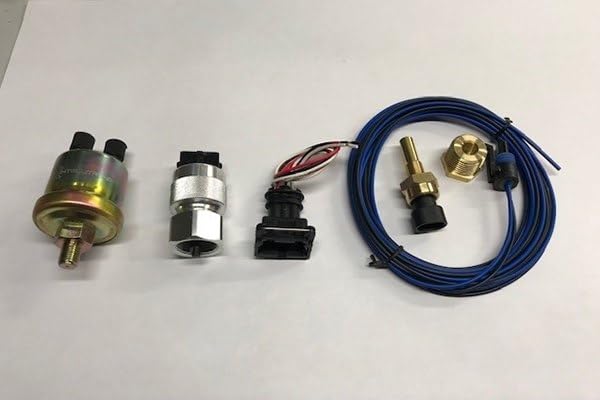
Image 2.2: Close-up of the included sending units, typically for oil pressure and water temperature, which are essential for the digital gauges to function.
3. Safety Information
Always prioritize safety during installation and operation. Failure to follow these guidelines may result in injury or damage to your vehicle.
- Disconnect the vehicle's battery before beginning any electrical work.
- Wear appropriate personal protective equipment, including safety glasses.
- Ensure all wiring connections are secure and properly insulated to prevent short circuits.
- Consult a professional automotive technician if you are unsure about any part of the installation process.
- This product is intended for use in 1992-1995 Jeep YJ vehicles only.
4. Installation Instructions
This section outlines the general steps for installing the Intellitronix LED Digital Gauge Panel. Specific wiring details may vary slightly based on your vehicle's existing harness. It is recommended to have a factory service manual for your Jeep YJ for reference.
4.1. Preparation
- Disconnect the negative terminal of your vehicle's battery.
- Carefully remove the existing instrument cluster from your Jeep YJ dashboard. Refer to your vehicle's service manual for specific removal procedures.
- Disassemble your original instrument cluster to separate the factory bezel/housing and the original indicator lights (turn signals, high beam, brake, 4WD). These components will be reused.
4.2. Gauge Panel Assembly
The Intellitronix gauge panel consists of circuit boards that fit into your existing factory bezel.

Image 4.1: The reverse side of the main circuit board, showing the wiring connections for the various digital gauges.

Image 4.2: Detailed view of the RPM gauge circuit board, indicating connections for power and signal input.
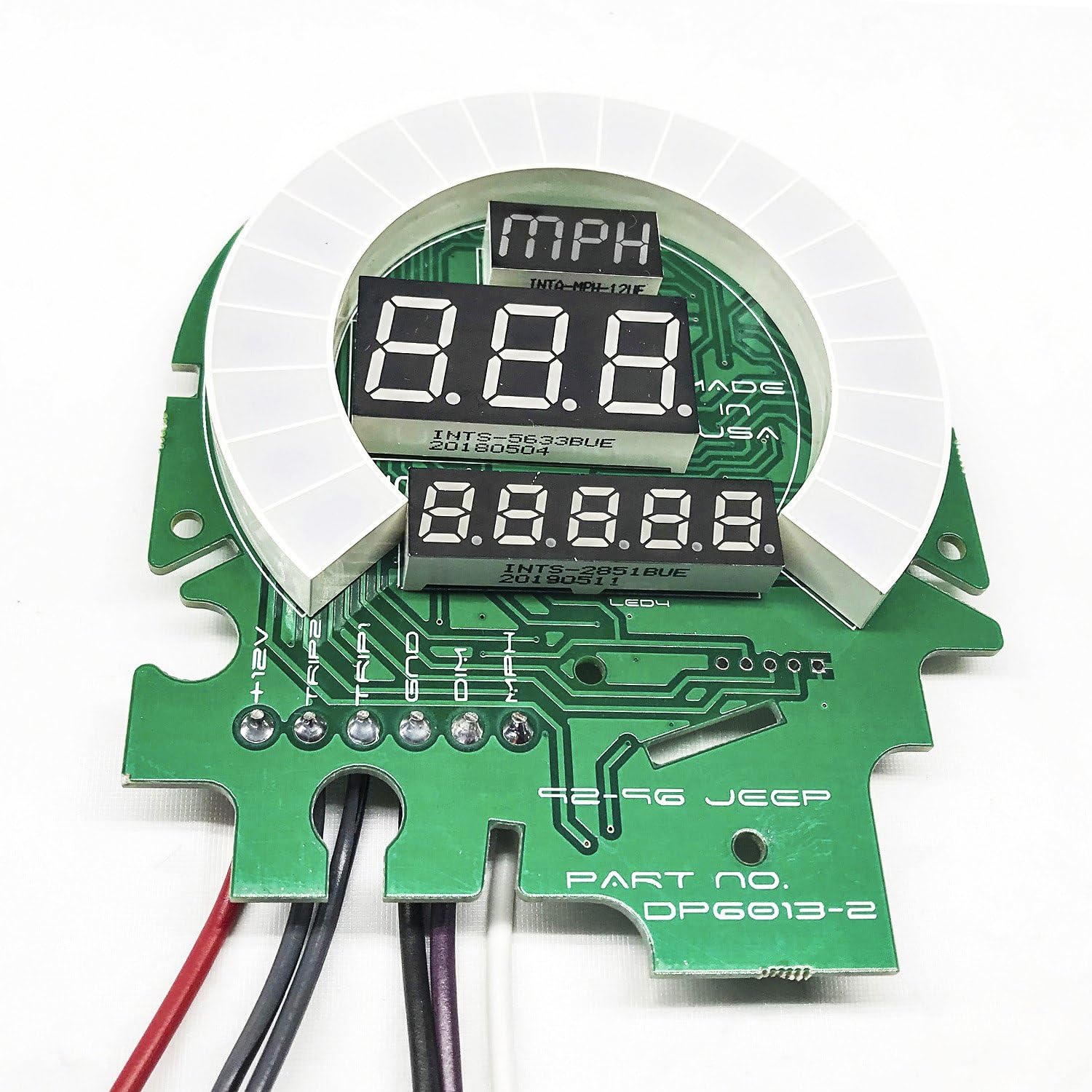
Image 4.3: Detailed view of the MPH gauge circuit board, showing connections for speed sensor input and power.
- Carefully install the Intellitronix circuit boards into your factory bezel. Ensure they are seated correctly and securely.
- Reinstall the original indicator lights (turn signals, high beam, brake, 4WD) into their respective positions on the factory bezel.
4.3. Wiring Connections
Connect the provided wiring harnesses to the Intellitronix gauge panel and to your vehicle's electrical system. Refer to the color-coded wires and the following guidelines:
- Power (12V Switched): Connect to a switched 12-volt source that is active when the ignition is on.
- Ground: Connect to a reliable chassis ground point.
- Illumination: Connect to your vehicle's dash illumination circuit for dimming functionality.
- Tachometer: Connect to the negative side of the ignition coil or a dedicated tachometer signal wire. Displays 0-9900 RPM in 100 RPM increments.
- Oil Pressure: Connect the provided oil pressure sending unit to the engine block's oil pressure port. Connect the sending unit wire to the gauge panel. Reads 0-100 PSI.
- Voltmeter: No separate sending unit required. Connect the voltmeter input wire to a 12-volt source. Displays 7.0-25.5 volt range.
- Fuel Level: Connect to your vehicle's existing fuel level sending unit wire. This gauge is programmable for Jeep/Chrysler, Ford, GM, VDO (10-180 ohms), and aftermarket (240-33 ohms) sending units.
- Water Temperature: Install the provided S8013 sending unit into an appropriate port on your engine's cooling system. Connect the sending unit wire to the gauge panel. Displays 100-300°F. A 1/2" bushing is typically supplied; if a 3/8" bushing is required, it must be sourced separately.
- Speedometer (MPH): Connect to your vehicle's speed sensor output.
Important: Ensure all connections are correct before reconnecting the battery.
4.4. Final Assembly
- Once all wiring is complete and secure, carefully reinstall the assembled gauge panel into your dashboard.
- Reconnect the negative terminal of your vehicle's battery.
- Turn the ignition to the "ON" position and verify that all gauges power on and display readings.
5. Operation
The Intellitronix LED Digital Gauge Panel provides real-time digital readouts for your vehicle's critical functions.
- Tachometer: Displays engine RPM.
- Oil Pressure: Shows engine oil pressure in PSI.
- Voltmeter: Indicates vehicle system voltage.
- Fuel Level: Displays remaining fuel as a percentage.
- Water Temperature: Shows engine coolant temperature in Fahrenheit.
- Speedometer: Displays vehicle speed in MPH.
The panel does not include a clock or integrated indicators for turn signals, high beam, brake, or 4WD. These functions rely on your original OEM dash indicators.
6. Calibration (Fuel Level)
The fuel level gauge requires calibration to match your vehicle's sending unit. Follow these steps:
- Ensure your fuel tank is either completely full or completely empty for accurate calibration.
- Locate the calibration button or jumper on the fuel gauge circuit board (refer to specific product diagrams if available).
- With the ignition on, press and hold the calibration button (or activate the jumper) until the display shows "CAL" or begins flashing.
- Release the button/jumper. The gauge will now read the current fuel level and store this as the full or empty reference point.
- Repeat the process for the opposite fuel level (empty if you calibrated full, or full if you calibrated empty) to set the full range.
The gauge supports various sending unit resistances: Jeep/Chrysler, Ford, GM, VDO (10-180 ohms), and aftermarket (240-33 ohms).
7. Maintenance
The Intellitronix LED Digital Gauge Panel is designed for long-term reliability and requires minimal maintenance.
- Keep the display clean using a soft, dry cloth. Avoid abrasive cleaners or solvents.
- Periodically check wiring connections for tightness and corrosion.
- Ensure sending units are free from debris and properly seated.
8. Troubleshooting
If you encounter issues with your gauge panel, refer to the following common problems and solutions:
| Problem | Possible Cause | Solution |
|---|---|---|
| Gauge does not power on. | No power connection, faulty ground, blown fuse. | Check 12V switched power connection, verify ground connection, inspect vehicle fuses. |
| Inaccurate gauge reading. | Incorrect sending unit, faulty sending unit, improper wiring, calibration issue (fuel). | Verify correct sending unit for the gauge, check sending unit functionality, inspect wiring for damage or loose connections, recalibrate fuel gauge. |
| Gauge flickers or displays erratic readings. | Loose wiring connection, electrical interference, poor ground. | Secure all wiring connections, ensure proper grounding, check for sources of electrical interference. |
| Fuel gauge reads incorrectly after installation. | Fuel gauge not calibrated. | Perform fuel gauge calibration as described in Section 6. |
If troubleshooting steps do not resolve the issue, please contact Intellitronix customer support for further assistance.
9. Specifications
- Model Number: DP6013
- Product Dimensions: 10 x 8 x 4 inches
- Item Weight: 3 Pounds
- Material: Acrylic
- Tachometer Range: 0-9900 RPM (100 RPM increments)
- Oil Pressure Range: 0-100 PSI
- Voltmeter Range: 7.0-25.5 Volts
- Fuel Level Range: 0-99% (1% increments), programmable for various sending units (10-180 ohms, 240-33 ohms)
- Water Temperature Range: 100-300°F (includes S8013 sending unit)
- UPC: 818731015923
10. Warranty and Support
Intellitronix products are backed by a manufacturer's warranty. For specific warranty details, registration, or technical support, please visit the official Intellitronix website or contact their customer service department.
Manufacturer: Intellitronix
Contact Information: Refer to the Intellitronix official website for the most current support contact details.


