
1. Introduction
This manual provides detailed instructions for the installation, operation, and maintenance of the Xiltek Dixell XR03CX-4N0F1 Digital Temperature Control Panel Thermostat. This device is designed for precise temperature management in refrigeration units, ensuring optimal performance and food safety. Please read this manual thoroughly before installation and operation to ensure correct usage and to prevent damage to the unit or connected equipment.
2. Safety Information
WARNING: Electrical Shock Hazard
- Always disconnect power before performing any installation, wiring, or maintenance procedures.
- Installation and wiring should only be performed by qualified personnel in accordance with all local and national electrical codes.
- Ensure the power supply voltage matches the specifications of the thermostat (120V).
- Do not expose the device to water or excessive humidity.
Failure to follow these safety instructions may result in electrical shock, fire, or serious injury.
3. Package Contents
Verify that all items are present and undamaged upon opening the package:
- 1x Dixell XR03CX-4N0F1 Digital Temperature Control Panel Thermostat
- 1x Blue Room Temperature Sensor Probe
- 1x Black Evaporator Temperature Sensor Probe
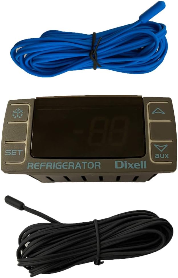
Image 3.1: The Dixell XR03CX-4N0F1 thermostat shown with both the blue room temperature probe and the black evaporator probe.

Image 3.2: Individual blue room temperature sensor probe and black evaporator temperature sensor probe.
4. Installation and Wiring
4.1 Mounting the Thermostat
The XR03CX-4N0F1 is designed for panel mounting. Ensure there is adequate space for ventilation around the unit.
4.2 Wiring Connections
Refer to the wiring diagram on the back of the thermostat and the images below for correct connections. All connections must be secure to prevent intermittent operation or damage.

Image 4.1: Rear view of the thermostat displaying the wiring diagram and terminal connections.

Image 4.2: Bottom view of the thermostat, highlighting the green terminal blocks for wiring.
- Power Supply (120V AC): Connect the main power supply to the designated terminals (typically marked 'Line' and 'Neutral' or similar, as per the diagram).
- Sensor Probes:
- Connect the blue room temperature probe to the 'Room' sensor input.
- Connect the black evaporator temperature probe to the 'Pb2' sensor input. Note: This controller typically uses one primary input for control, often the room probe, while the second probe may be used for defrost management or display.
- Compressor Output: Connect the compressor control wiring to the 'Comp' output terminals.
- Fan Output: Connect the fan control wiring to the 'Fan' output terminals (if applicable).
- Auxiliary Output: If your system utilizes an auxiliary function, connect it to the 'Aux' output terminals.
IMPORTANT: Double-check all wiring connections before applying power to the unit.
5. Operating Instructions
The XR03CX-4N0F1 features a clear digital display and intuitive buttons for operation.

Image 5.1: Front view of the thermostat, showing the digital display and control buttons.
5.1 Display
The digital display shows the current temperature measured by the primary sensor. It may also show various icons indicating operational status (e.g., compressor running, defrost cycle).
5.2 Control Buttons
- SET Button: Used to view or modify the setpoint temperature and access programming parameters.
- UP Arrow Button (▲): Used to increase values or scroll through menu options.
- DOWN Arrow Button (▼): Used to decrease values or scroll through menu options.
- AUX Button: May activate auxiliary functions or serve as an escape/exit button in programming mode.
- Defrost Button (Snowflake/Water Droplet Icon): Initiates a manual defrost cycle.
5.3 Setting the Temperature Setpoint
- Press and release the SET button. The current setpoint value will flash on the display.
- Use the UP (▲) or DOWN (▼) arrow buttons to adjust the setpoint to the desired temperature.
- Press the SET button again to confirm the new setpoint and exit. If no button is pressed for several seconds, the display will revert to showing the current temperature without saving changes.
5.4 Manual Defrost
To initiate a manual defrost cycle, press and hold the Defrost button (snowflake/water droplet icon) for approximately 3 seconds. The defrost cycle will begin according to the programmed parameters.
6. Maintenance
6.1 Cleaning
To clean the thermostat's front panel, use a soft, damp cloth. Do not use abrasive cleaners, solvents, or harsh chemicals, as these can damage the display or casing.
6.2 Sensor Inspection
Periodically inspect the temperature sensor probes for any signs of damage, corrosion, or loose connections. Ensure they are properly positioned within the refrigeration unit for accurate temperature readings.
7. Troubleshooting
If you encounter issues with your XR03CX-4N0F1 thermostat, refer to the following common problems and solutions:
| Problem | Possible Cause | Solution |
|---|---|---|
| Display is blank | No power supply; loose wiring | Check power connections and ensure 120V supply. Verify all wiring is secure. |
| Temperature reading is inaccurate | Faulty sensor probe; incorrect probe placement | Inspect sensor probes for damage. Ensure probes are correctly positioned and making good contact. Replace if faulty. |
| Compressor not running | Setpoint too high; compressor lockout; wiring issue | Lower the setpoint. Check for any error codes. Verify compressor wiring. Consult a technician if problem persists. |
| Error code on display (e.g., 'P1', 'E1') | Sensor fault; internal error | Refer to the Dixell XR03CX technical manual for specific error code meanings. Often indicates a sensor issue. |
For complex issues or if troubleshooting steps do not resolve the problem, it is recommended to contact a qualified refrigeration technician or Xiltek customer support.
8. Specifications
| Feature | Detail |
|---|---|
| Model | XR03CX-4N0F1 |
| Brand | Xiltek (Dixell Manufacturer) |
| Voltage | 120 Volts |
| Material | Plastic |
| Display Type | LCD |
| Item Weight | 1 pound |
| UPC | 689227216922 |
| Included Components | Thermostat, 2 Temperature Sensor Probes |
| Application | Refrigerator Temperature Control |
9. Warranty and Support
This Dixell thermostat is supplied by Xiltek. For warranty information or technical support, please contact Xiltek directly. Keep your purchase receipt as proof of purchase for any warranty claims.
For additional resources or to contact support, visit the Xiltek Store on Amazon.