1. Introduction and Overview
This manual provides detailed instructions for the installation, operation, and maintenance of your EPEVER 30A24V PWM Solar Charge Controller. Please read this manual thoroughly before installation and use to ensure optimal performance and safety of your solar power system.
The EPEVER 30A24V controller is designed to manage the power flow from your solar panels to your battery bank, preventing overcharging and over-discharging, and extending battery life. It features an LCD display for real-time monitoring and dual USB outputs for charging external devices.

Figure 1: Front view of the EPEVER 30A24V Solar Charge Controller.

Figure 2: Examples of solar charge controller applications in residential and commercial settings.
2. Product Features
- High Quality and Safety: Utilizes high-quality components from ST, IR, and Infineon. Terminals are UL and VDE certified, ensuring product longevity and reliability.
- LCD Display: Provides real-time display of solar panel and battery performance, along with an energy statistics counter. Features user-friendly buttons for convenient operation.
- Dual USB Output: Offers fast and powerful charging for USB-compatible devices such as mobile phones, tablets, and MP3 players.
- 3-Stage Charging: Supports three battery types: Sealed, Gel, and Flooded. Implements 3-stage PWM intelligent charging: Bulk, Boost/Equalize, and Float. Includes multiple load control modes: light control, light time control, and dual time control.
- Multiple Protections: Comprehensive protection features including PV reverse polarity, battery reverse polarity, battery overvoltage, battery over-discharge, battery overheating, load short circuit, load overload, and controller overheating (up to 55℃).

Figure 3: Detail showing the dual USB ports and the heat dissipation aluminum alloy design.
3. Product Components
Familiarize yourself with the different parts of your EPEVER solar charge controller:
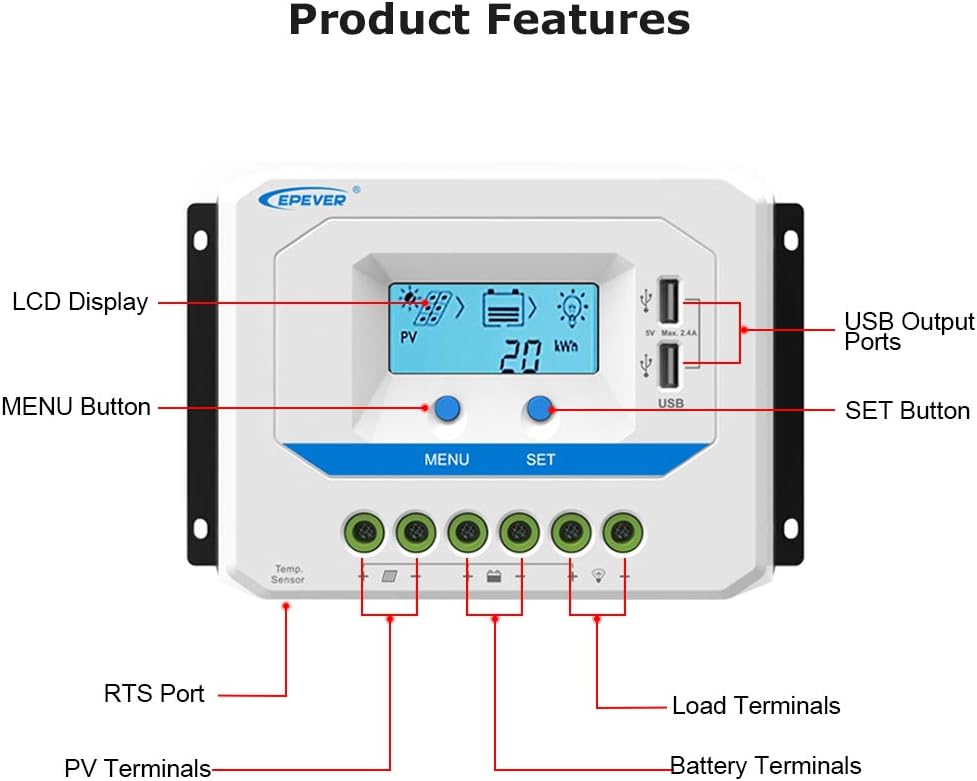
Figure 4: Labeled components of the EPEVER Solar Charge Controller.
- LCD Display: Shows system status and parameters.
- USB Output Ports: For charging external USB devices (5V, Max 2.4A).
- MENU Button: Used to navigate through display screens and settings.
- SET Button: Used to confirm selections and modify parameters.
- RTS Port: Remote Temperature Sensor port.
- PV Terminals: Connect to solar panel input.
- Battery Terminals: Connect to battery bank.
- Load Terminals: Connect to DC loads.
4. Setup and Installation
Proper installation is crucial for the safe and efficient operation of your solar charge controller. Follow these steps carefully:
- Mounting: Choose a dry, well-ventilated location away from direct sunlight and heat sources. Ensure adequate air circulation around the controller for heat dissipation.
- Wiring Sequence: It is critical to connect components in the correct order to prevent damage to the controller or other system components.
- First, connect the Battery (1) to the battery terminals on the controller. Ensure correct polarity (+ to + and - to -).
- Second, connect the Solar Panel (3) to the PV terminals on the controller. Ensure correct polarity.
- Third, connect the DC Load (2) to the load terminals on the controller. Ensure correct polarity.
- Disconnection Sequence: When disconnecting the system, reverse the wiring sequence: disconnect the load first, then the solar panel, and finally the battery.
- Safety Precautions: Always install appropriate breakers and fuses between the controller and the battery, and between the solar panel and the controller, as shown in the wiring diagram.

Figure 5: Detailed wiring diagram for the solar charge controller, battery, solar panel, and load. Numbers indicate connection sequence.
5. Operating Instructions
5.1. Battery Type Selection
The controller supports three types of batteries: Sealed, Gel, and Flooded. It is essential to select the correct battery type for optimal charging and battery longevity.

Figure 6: Visual representation of battery type selection on the LCD display.
- Sealed (Default): For sealed lead-acid batteries.
- Gel: For gel batteries.
- Flooded: For flooded lead-acid batteries.
To change the battery type, press the MENU button to navigate to the battery type setting, then use the SET button to cycle through the options and confirm your selection.
5.2. LCD Display Information
The LCD display provides real-time information about your solar system's performance:
- PV (Photovoltaic) Status: Indicates solar panel input.
- Battery Status: Shows battery charge level and voltage.
- Load Status: Indicates whether the load is active.
- kWh: Displays accumulated energy generated or consumed.
- Current and Voltage Readings: Detailed readings for PV, battery, and load.
Press the MENU button to cycle through different display screens and view various parameters.
6. Maintenance
Regular maintenance ensures the longevity and optimal performance of your solar charge controller:
- Cleanliness: Keep the controller clean and free from dust and debris. Use a dry cloth to wipe the surface.
- Connections: Periodically check all wiring connections to ensure they are tight and secure. Loose connections can cause overheating and performance issues.
- Ventilation: Ensure that the controller's heat sink (aluminum alloy fins) is not obstructed and has proper airflow for efficient heat dissipation.
- Battery Inspection: Regularly inspect your batteries for any signs of corrosion, swelling, or leakage. Ensure battery terminals are clean.
- System Monitoring: Monitor the LCD display regularly for any error codes or unusual readings.
7. Troubleshooting
This section provides solutions to common issues you might encounter with your solar charge controller:
| Problem | Possible Cause | Solution |
|---|---|---|
| Controller LCD is off / No power | Battery not connected or reverse polarity; Battery voltage too low. | Check battery connections and polarity. Charge battery if voltage is below minimum operating level. |
| Battery not charging | Solar panel not connected or reverse polarity; Insufficient sunlight; PV voltage too low. | Check solar panel connections and polarity. Ensure panels are in direct sunlight. Verify PV voltage is within controller's operating range. |
| Load not working | Load short circuit; Overload; Battery low voltage disconnect; Load output disabled. | Check load wiring for short circuits. Reduce load. Allow battery to recharge. Check load control settings on controller. |
| Controller overheating | Poor ventilation; Excessive load. | Ensure adequate airflow around the controller. Reduce load if consistently overheating. |
8. Specifications
Detailed technical specifications for the EPEVER 30A24V Solar Charge Controller:

Figure 7: Physical dimensions of the VS3024AU model.
| Attribute | Value |
|---|---|
| Manufacturer | EPEVER® |
| Model | VS3024AU (30A24V) |
| Charging Port Type | USB (Dual, 5V Max 2.4A) |
| Package Dimensions | 20.6 x 12.1 x 7.8 cm |
| Weight | 671 g |
| Certifications | UL, VDE (for terminals) |
| Batteries Required | No (for controller operation) |
| ASIN | B081GS3X3B |
| UPC | 732376582667 |
| Voltage | 12V/24V Automatic Work |
| Display Type | LCD |
9. Warranty and Support
EPEVER products are designed for reliability and performance. For technical assistance, troubleshooting beyond this manual, or warranty inquiries, please contact EPEVER customer support directly. Please have your product model number (VS3024AU or 30A24V) and purchase information ready when contacting support.
While third-party protection plans may be available, any manufacturer's warranty claims should be directed to EPEVER.


