1. Product Overview
The OBO HANDS Full Metal Access Control Kit provides a comprehensive solution for secure entry management. This kit includes a robust access control keypad, a DC 12V electric drop lock, a 12V 3A power supply, a door exit button, and 10 RFID 125 KHz keyfobs. Designed for reliability and ease of use, it supports up to 1000 users with multiple access methods.

Image 1.1: All components of the OBO HANDS Full Metal Access Control Kit, including the keypad, electric drop lock, power supply, exit button, and 10 RFID keyfobs.
Key Features:
- Access Controller: Supports 1000 standard users with RFID card, password, or RFID card + password access methods. Features a sensitive and fast response keypad with backlight and a doorbell button. Includes WG26 interface and 2-relay output with time delay and tamper alarm functions.
- Power Supply: DC 12V/3A output, AC90-260V input. Adjustable delay from 0-30 seconds. High-quality metal construction with low power consumption.
- Electric Drop Lock: NC (Fail Safe) mode, meaning it locks when powered and unlocks without electricity. Features 0s, 3s, 6s delay settings and a durable, wear-resistant surface treatment. Secured with hexagonal screws for anti-theft.
- Exit Button: Made of hard plastic, rated for 250,000 cycle tests. Supports both NC (Fail Safe) and NO (Fail Secure) modes.
- RFID Keyfobs: 10 blue 125 KHz TK4100 read-only keyfobs, each pre-programmed with a unique ID. Waterproof ABS material.
2. Setup and Installation
Careful installation is crucial for the proper functioning and security of your access control system. Ensure all power is disconnected before beginning installation.
2.1 Access Control Keypad Installation
The keypad is designed for surface mounting. Choose a secure, weather-protected location near the entry point. Connect the keypad to the power supply and electric lock according to the wiring diagram (refer to the power supply section for terminal details).

Image 2.1: Detailed view of the access control keypad, highlighting its aluminum material, waterproof surface, backlit keys, and internal CPU for stable operation.
- Mount the keypad securely to a wall or door frame using appropriate screws.
- Connect the power wires (DC12V), lock control wires (NC/NO/COM), and exit button wires (PUSH/GND) to the keypad's terminals.
- If desired, connect a doorbell to the doorbell terminals.
- Ensure all connections are tight and insulated.
2.2 Electric Drop Lock Installation
The electric drop lock is typically installed on the door frame and the corresponding strike plate on the door. Ensure proper alignment for secure locking.
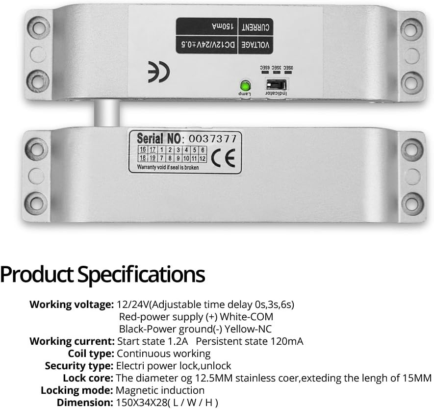
Image 2.2: Close-up of the electric drop lock, showing its serial number and basic specifications. This lock operates in NC (Fail Safe) mode.
- Mount the main body of the lock to the door frame and the armature plate to the door, ensuring they align perfectly when the door is closed.
- Connect the lock's power wires to the power supply's NC/NO/COM terminals as required by your system configuration (NC mode is default for this lock).
- Test the lock's operation manually before applying power.
2.3 Power Supply Installation
The power supply unit converts AC power to DC 12V for the system and manages the lock's power. It should be installed in a dry, secure location.

Image 2.3: The power supply control unit, showing input (AC110-260V) and output (DC12V 3A) specifications, along with control terminals for the access system.
- Mount the power supply unit to a wall.
- Connect the AC input (AC100-260V) to a suitable power source.
- Connect the keypad's DC12V and GND to the power supply's +12V and GND terminals.
- Connect the electric lock to the NC/NO/COM terminals based on the lock type and desired operation. For the included electric drop lock, use NC and COM.
- Connect the exit button to the PUSH and GND terminals.
- The delay for the lock can be adjusted from 0 to 30 seconds using the potentiometer on the power supply board.
2.4 Door Exit Button Installation
The exit button allows for convenient egress from the secured area.

Image 2.4: The door exit button, showing its design, material (hard plastic), and dimensions (85x85mm). It supports both NC and NO modes.
- Mount the exit button on the inside of the door, at a convenient height.
- Connect the button's wires to the PUSH and GND terminals on the power supply unit.
3. Operating Instructions
Once installed and powered, the system is ready for programming and operation.
3.1 Initial Setup and Programming
- Enter Programming Mode: Press * then enter the default master password (usually 123456 or 999999, refer to specific keypad manual if different), then #.
- Change Master Password: In programming mode, follow the keypad's specific instructions to change the master password for security.
- Add User Cards/Passwords:
- To add an RFID card: Enter programming mode, select 'add user card' option, then present the RFID keyfob to the keypad.
- To add a user password: Enter programming mode, select 'add user password' option, then enter the desired 4-6 digit password.
- To add a card + password user: Enter programming mode, select 'add card+password' option, present the RFID keyfob, then enter the desired password.
- Delete User Cards/Passwords: In programming mode, select 'delete user' option, then enter the user ID or present the card to be deleted.
- Exit Programming Mode: Press * to exit programming mode.

Image 3.1: A set of 10 blue 125 KHz RFID keyfobs. Each keyfob is pre-programmed with a unique identity and is waterproof.
3.2 Daily Operation
- Access by RFID Card: Present a registered RFID keyfob to the keypad. The lock will disengage for the set delay time.
- Access by Password: Enter a registered password on the keypad, then press #. The lock will disengage for the set delay time.
- Access by RFID Card + Password: Present a registered RFID keyfob, then enter the associated password, then press #. The lock will disengage.
- Exiting: Press the door exit button to disengage the lock from the inside.
- Doorbell Function: Press the doorbell button on the keypad to activate the connected doorbell.
4. Maintenance
Regular maintenance ensures the longevity and reliable operation of your access control system.
- Cleaning: Wipe the keypad and other components with a soft, damp cloth. Avoid abrasive cleaners or solvents.
- Inspection: Periodically check all wiring connections for tightness and signs of wear or damage.
- Lock Mechanism: Ensure the electric drop lock operates smoothly and is free from obstructions. Keep the lock mechanism clean.
- Keyfobs: Store RFID keyfobs in a safe place and avoid exposing them to extreme temperatures or physical damage.
- Software/Firmware: This system typically does not require software updates. If advanced features are desired, consult the manufacturer.
5. Troubleshooting
If you encounter issues with your access control system, refer to the following troubleshooting guide:
| Problem | Possible Cause | Solution |
|---|---|---|
| Keypad does not power on. | No power to the power supply; faulty wiring; power supply failure. | Check AC input to power supply. Verify DC 12V output. Inspect all wiring connections. |
| Lock does not engage/disengage. | Incorrect wiring (NC/NO); insufficient power; lock mechanism obstruction; faulty lock. | Ensure lock is wired to NC and COM terminals for Fail Safe operation. Check power supply output. Clear any obstructions. Test lock independently if possible. |
| RFID card/password not recognized. | Card/password not programmed; incorrect entry; faulty card. | Verify card/password is correctly programmed (refer to Section 3.1). Re-enter password carefully. Try a different registered card. |
| Exit button does not work. | Incorrect wiring; faulty button. | Check wiring between exit button and power supply (PUSH/GND). Test button continuity if possible. |
| Tamper alarm activates unexpectedly. | Keypad tampered with; sensitive setting. | Inspect keypad for physical damage. Consult keypad manual for alarm sensitivity adjustment. |
6. Specifications
Detailed technical specifications for the OBO HANDS Access Control Kit components:
6.1 Access Control Keypad
- User Capacity: 1000 standard users
- Access Modes: RFID Card, Password, RFID Card + Password
- Interface: WG26
- Output: 2 Relays
- Features: Backlit numeric keypad, doorbell button, time delay, tamper alarm
- Material: Full Metal (Aluminum)
6.2 Power Supply
- Input Voltage: AC 90-260V, 50-60Hz
- Output Voltage: DC 12V
- Output Current: 3A
- Delay Adjustment: 0-30 seconds
- Dimensions: 140 x 67 x 33 mm (L/W/H)
6.3 Electric Drop Lock
- Operating Mode: NC (Fail Safe - Locked when powered, Unlocked without power)
- Installation: Surface Mount
- Delay Settings: 0s, 3s, 6s
- Dimensions: 150 x 34 x 28 mm (L/W/H)
- Security: Hexagonal screw body, anti-theft fixed panel
6.4 Door Exit Button
- Material: Hard Plastic
- Cycle Test: 250,000 tests
- Output: Two contact outputs (NC/NO compatible)
- Dimensions: 85 x 85 mm (L/W)
6.5 RFID Keyfobs
- Frequency: 125 KHz
- Chip Type: TK4100 (Read-only)
- Material: Waterproof ABS
- Quantity: 10 pieces
7. Warranty and Support
For warranty information and technical support, please refer to the documentation provided with your purchase or contact your retailer. Information regarding spare parts availability is not provided with this manual.
Always ensure that installation and maintenance are performed by qualified personnel to prevent damage or injury.


