1. Product Overview
The EPEVER Tracer2210AN G3 is an advanced Maximum Power Point Tracking (MPPT) solar charge controller designed for efficient and reliable charging of various battery types from solar panels. It automatically detects 12V/24V battery systems and supports a maximum PV input voltage of 100V. This controller is equipped with an LCD display for real-time data viewing and parameter setting, and features multiple load control modes for versatile application.
Key features include support for Sealed lead acid, AGM, GEL, Flooded, and Lithium batteries (LiFePO4, Li(NiCoMn)O2), common negative ground design, and PC software compatibility for enhanced monitoring and control.

Figure 1: EPEVER Tracer2210AN G3 MPPT Solar Charge Controller and its packaging.

Figure 2: Top and bottom views of the Tracer2210AN G3, highlighting model specifications and terminal layout.
2. Features
- Advanced MPPT Technology: Ensures maximum power point tracking for optimal solar panel efficiency.
- Automatic System Voltage Recognition: Automatically detects 12V or 24V battery systems.
- Wide PV Input Range: Supports a maximum PV voltage of 100V.
- High Power Capacity: Max. PV input power of 260W for 12V systems and 520W for 24V systems.
- Versatile Battery Compatibility: Supports Sealed lead acid, AGM, GEL, Flooded, LiFePO4 (4s/12V; 8s/24V), Li(NiCoMn)O2 (3s/12V; 6s/24V), and user-defined battery types (9~34V).
- Common Negative Ground: Designed with common negative grounding for system compatibility.
- Backlight LCD Display: Provides clear real-time data and allows for easy parameter adjustments.
- PC Software Support: Compatible with PC (Windows) software and MT50 for convenient data viewing and parameter configuration.
- Multiple Load Control Modes: Includes manual mode, light ON/OFF, light On+ Timer, and test mode for flexible load management.
- Communication Port Protection: Features a professional protection chip on the communication port, providing 5VDC power supply.

Figure 3: Supported battery types for the Tracer2210AN G3 controller.
3. Setup and Installation
Proper installation is crucial for the safe and efficient operation of your solar charge controller. Please follow these steps carefully.
3.1 Wiring Sequence
- Connect the Battery: First, connect the battery to the charge controller. Ensure correct polarity. The controller will automatically detect the battery voltage (12V or 24V).
- Connect the Solar Panel: Next, connect the solar panel(s) to the charge controller. Ensure correct polarity. The controller will begin charging the battery.
- Connect the DC Load: Finally, connect the DC load to the charge controller. Ensure correct polarity.
Important: Always connect the battery first and disconnect the solar panel and load before disconnecting the battery.
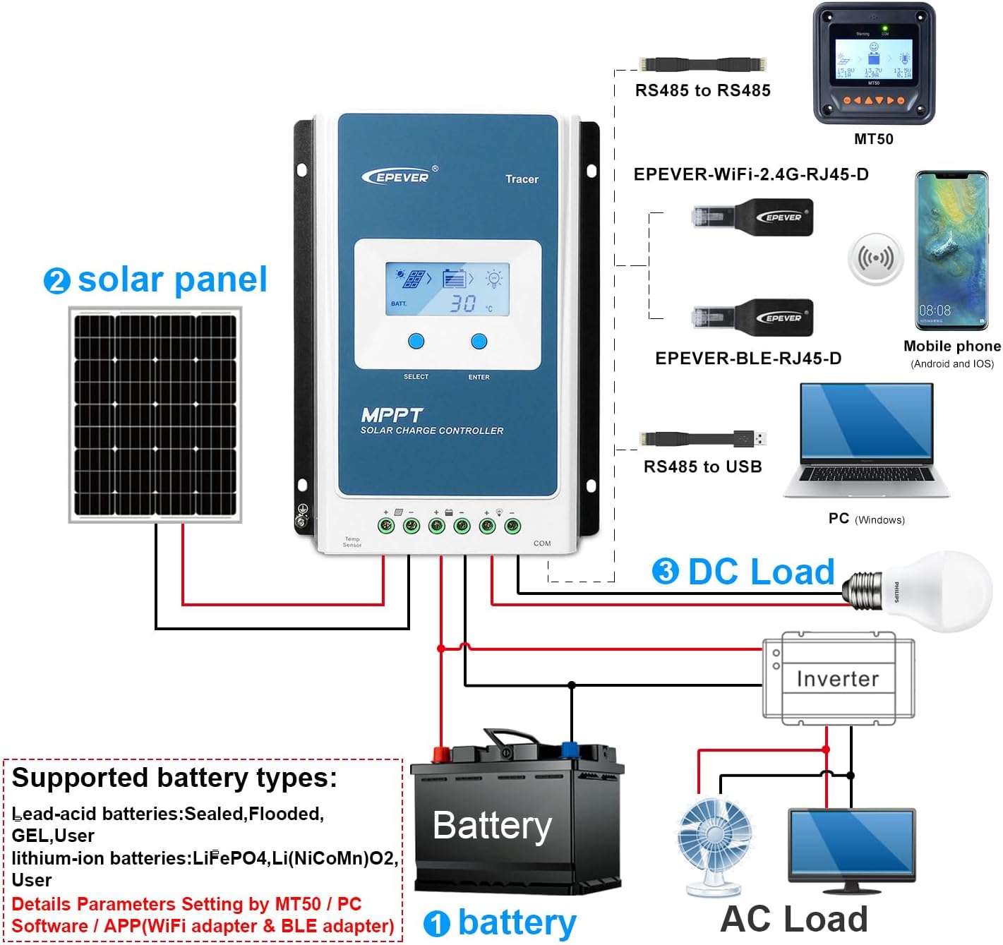
Figure 4: System connection diagram for the Tracer2210AN G3.

Figure 5: Simplified connection diagram illustrating solar panel, battery, and load connections.
3.2 Mounting
Mount the controller vertically on a flat, non-flammable surface in a well-ventilated area, away from direct sunlight, high temperatures, and water. Ensure sufficient clearance around the controller for proper heat dissipation.
4. Operating Instructions
The Tracer2210AN G3 features an intuitive LCD display and control buttons for easy operation and monitoring.
4.1 LCD Display and Button Functions
The LCD displays various system parameters such as battery voltage, charging current, load current, and temperature. Use the "SELECT" and "ENTER" buttons to navigate through menus and adjust settings.

Figure 6: LCD display interfaces and battery type setting process.
4.2 Setting Battery Type
The controller supports various battery types. It is crucial to set the correct battery type for optimal charging and battery longevity. Refer to Figure 6 for visual guidance.
- Press the "ENTER" button to enter the main menu.
- Navigate using "SELECT" to find the battery type setting option.
- Press "ENTER" to select, then use "SELECT" to choose your battery type (e.g., Sealed, Gel, Flooded, LiFePO4, Li(NiCoMn)O2, User).
- Press "ENTER" to confirm your selection.
For user-defined battery types, you can set specific voltage parameters (e.g., charge voltage, low voltage disconnect) via the PC software or MT50.
4.3 Load Control Modes
The controller offers four load control modes:
- Manual Mode: Load can be turned ON/OFF manually via the controller buttons.
- Light ON/OFF: Load turns ON at dusk and OFF at dawn.
- Light On+ Timer: Load turns ON at dusk and stays ON for a set duration.
- Test Mode: For testing purposes, typically keeps the load ON.
These modes can be configured through the LCD display or the PC software.
4.4 PC Software and MT50
For advanced monitoring and parameter setting, connect the controller to a PC (Windows) using the appropriate communication cable (e.g., RS485 to USB) or use the MT50 remote meter. This allows for detailed data logging, custom battery parameters, and firmware updates.
5. Maintenance
Regular maintenance ensures the longevity and optimal performance of your solar charge controller.
- Cleanliness: Keep the controller clean and free from dust and debris. Use a dry cloth for cleaning.
- Connections: Periodically check all wiring connections to ensure they are tight and free from corrosion. Loose connections can cause overheating and damage.
- Ventilation: Ensure that the ventilation openings are not blocked to allow for proper heat dissipation.
- Environmental Conditions: Ensure the controller is operating within its specified temperature range (Operating Temperature: 25 Degrees Celsius, though typically wider for electronics). Avoid exposure to extreme humidity or direct water.
- Battery Health: Monitor your battery's health and ensure it is properly maintained according to its type (e.g., checking electrolyte levels for flooded batteries).
6. Troubleshooting
The Tracer2210AN G3 incorporates various protection mechanisms. Understanding these can help in diagnosing and resolving common issues.

Figure 7: Protection mechanisms of the Tracer2210AN G3.
6.1 Common Protections and Solutions
- PV Over Current/Power: If the charging current or power from the PV array exceeds the rated current or power, the controller will limit it. Ensure PV modules are in series to prevent open-circuit voltage from exceeding the maximum PV open-circuit voltage.
- PV Short Circuit: When the PV array is short-circuited, the controller will not be damaged. The controller will resume normal operation once the short circuit is removed.
- PV Reverse Polarity: If the PV array is connected with reverse polarity, the controller will not be damaged. Correct the wiring to resume operation.
- Night Reverse Charging: Prevents the battery from discharging through the PV module at night.
- Battery Reverse Polarity: Fully protected against battery reverse polarity; no damage to the controller will result. Correct the miswire to resume normal operation.
- Battery Over Voltage: When the battery voltage reaches the over voltage disconnect voltage, the controller automatically stops battery charging.
- Battery Over Discharge: When the battery voltage reaches the low voltage disconnect voltage, the controller automatically stops battery discharging. Loads directly connected to the battery will not be affected.
- Battery Overheating: The controller can detect battery temperature through an external temperature sensor. Charging stops when temperature exceeds 65°C and begins working when below 55°C.
- Lithium Battery Low Temperature: If the temperature detected by the optional temperature sensor is lower than the Low Temperature Protection Threshold (LTPT), the controller will stop charging and discharging automatically. When the detected temperature is higher than the LTPT, the controller will resume operation.
- Load Short Circuit: If the load short circuit current is 2-4 times the rated load current, the controller will automatically cut off the output. It will reconnect automatically after 5s, 10s, 15s, 20s, 25s.
- Load Overload: If the load current is 1.05-1.25 times the rated load current, the controller will automatically cut off the output. It will reconnect automatically after 5s, 10s, 15s, 20s, 25s.
- Controller Overheating: The controller is able to detect the temperature inside the battery through an optional remote sensor. The controller stops working when its temperature exceeds 85°C and begins working when its temperature is below 75°C.
- TVS High Voltage Transients: The internal circuitry is designed with Transient Voltage Suppressors (TVS) which can only protect against high-voltage surge pulses with less energy. For stronger protection, an external surge arrester is recommended.
Note: When the internal battery temperature is 81°C, the charging power reducing mode will reduce the charging power by 5%, 10%, 20%, 40% every increase of 1°C. If the internal temperature is greater than 85°C, the controller will stop charging. While the temperature declines to below 75°C, the controller will resume.
7. Specifications
Detailed technical specifications for the EPEVER Tracer2210AN G3 MPPT Solar Charge Controller.
| Specification | Value |
|---|---|
| Model Number | Tracer2210AN G3 |
| Charge/Discharge Current | 20A |
| System Voltage | 12V/24V Auto Work |
| Max PV Input Voltage | 100V |
| Max. PV Input Power (12V) | 260W |
| Max. PV Input Power (24V) | 520W |
| Operating Temperature | 25 Degrees Celsius (typical range is wider, refer to full manual) |
| UPC | 791280364424 |
| Manufacturer | EPEVER |
| Charging Port Type | USB (for communication, not charging) |
| Package Dimensions | 9.45 x 6.3 x 2.76 inches |
| Item Weight | 2.64 pounds |
| Material | Aluminum |
| Display Type | LCD |

Figure 8: Physical dimensions of the Tracer2210AN G3.

Figure 9: Comparison of Tracer AN series models, including Tracer2210AN.
8. Warranty and Support
For any questions, technical assistance, or warranty claims, please consult the customer service of your retailer or the manufacturer directly. It is recommended to read the instruction manual carefully to avoid damage due to improper operation.
Please refer to the official EPEVER website or your purchase documentation for detailed warranty terms and conditions.


