1. Introduction
The EPEVER 40A MPPT Solar Charge Controller, model 4210AN, is an advanced Maximum Power Point Tracking (MPPT) charge controller designed for off-grid solar systems. It automatically identifies 12V/24V system voltages and is negatively grounded. This controller supports various battery types, including lead-acid (sealed, AGM, gel, flooded) and lithium batteries, and features automatic limitation of charging current and power. It offers high tracking efficiency of no less than 99.5% and a maximum DC/DC conversion efficiency of 98%.
2. Safety Information
- Ensure proper grounding of the controller before any connections.
- Always connect the battery first, then the solar panels (PV array), and finally the load. Disconnect in the reverse order.
- Verify correct polarity for all connections to prevent damage to the controller and connected devices.
- Install the controller in a well-ventilated area, away from flammable materials and direct sunlight.
- Use appropriate wire gauges for all connections to handle the expected current.
- Do not attempt to disassemble or repair the controller yourself. Contact qualified personnel for service.
3. Product Features
- Advanced MPPT Technology: Ensures maximum power point tracking with efficiency no less than 99.5%.
- High Conversion Efficiency: Maximum DC/DC conversion efficiency of 98%.
- Automatic Voltage Recognition: Supports 12V/24V auto-identifying system voltage.
- Multi-Battery Support: Compatible with lead-acid (Sealed, AGM, Gel, Flooded) and lithium batteries (LiFePO4, Li(NiCoMn)O2).
- Comprehensive Electronic Protection: Includes PV over-current, PV short circuit, PV reverse polarity, night charging, battery over-discharge, battery over-voltage, battery over-heating, lithium battery low temperature, load short circuit, overload, controller over-voltage, and TVS high voltage transients.
- Real-time Energy Recording: Provides statistical data and multiple load work modes.
- Communication Interface: Features a power protection chip (5VDC/200mA) and supports monitoring and parameter setting via APP or PC software.
- Battery Temperature Compensation: Ensures optimal charging and extends battery life.
4. Package Contents
The standard package for the EPEVER MPPT Solar Charge Controller includes the following items:
- EPEVER MPPT Solar Charge Controller (Model 4210AN)
- User Manual
- Temperature Sensor
- Certificate of Quality
Video: Unboxing and overview of the EPEVER MPPT Solar Charge Controller and its components.
5. Product Overview
The EPEVER 40A MPPT Solar Charge Controller features a clear LCD display and intuitive buttons for easy operation. Key interfaces include the temperature sensor port, PV input terminals, battery terminals, load output terminals, and an RS485 communication interface for PC/Bluetooth/WiFi modules.

Image: Front view of the EPEVER 40A MPPT Solar Charge Controller, highlighting its LCD display, control buttons, and key performance metrics like 99.5% MPPT tracking efficiency and 98% DC/DC conversion.

Image: Dimensional drawing of the EPEVER 40A MPPT Solar Charge Controller, showing its length (7.09"), width (2.48"), and height (9.92").
6. Installation
6.1 Wiring Sequence
Follow the correct wiring sequence to ensure safe and proper operation:
- Grounding: First, properly ground the controller.
- Battery Connection: Connect the battery to the controller's battery terminals.
- Temperature Probe: Connect the temperature probe to the designated port.
- PV Array Connection: Connect the solar panels (PV array) to the controller's PV input terminals.
- Load Connection: Connect the DC load to the controller's load output terminals.
To disconnect the system, follow the reverse order: disconnect the load, then the PV array, and finally the battery.
Video: Step-by-step guide on how to properly connect the EPEVER MPPT Solar Charge Controller, including grounding, battery, temperature probe, PV, and load connections.
6.2 System Wiring Diagrams
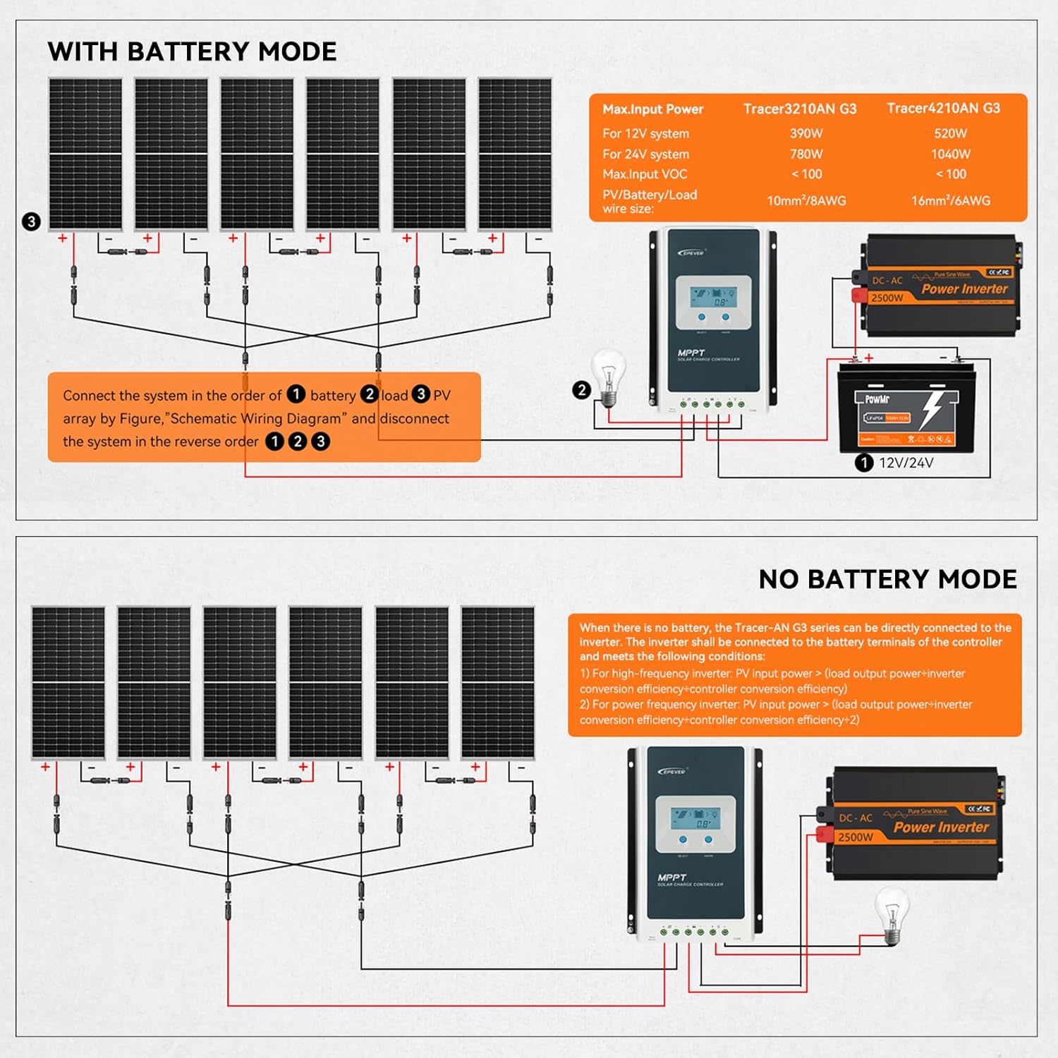
Image: Schematic wiring diagram for a solar system including the EPEVER controller, PV array, battery, and an optional inverter, showing connections for a system with battery storage.

Image: Schematic wiring diagram for a solar system using the EPEVER controller in 'No Battery Mode', where the PV array directly powers an inverter without battery storage.
7. Operation
7.1 Setting Battery Type
The controller supports various battery types. You can select the appropriate battery type via the LCD display and buttons. For lithium batteries, you can choose between LiFePO4 (4S/8S) and Li(NiCoMn)O2 (3S/6S/7S) or a user-defined setting.
Video: Demonstrates how to select the lithium battery type using the LCD and buttons on the controller. It explains that 'F' stands for LiFePO4 and 'N' for ternary lithium battery, with numbers indicating the string count.

Image: A table detailing the applicable battery types, including Sealed Lead Acid, Gel, Flooded, 4-Series LiFePO4, 8-Series LiFePO4, 3-Series Lithium-ion, 6-Series Lithium-ion, 7-Series Lithium-ion, and User-Defined options, with their corresponding display codes.
7.2 Load Work Modes
The controller offers multiple load work modes to suit different application needs:
- Timer Mode (1-14 Hrs): Load operates for a set duration after sunset.
- Manual Mode: Load can be manually turned on or off.
- Test Mode: For system testing and diagnostics.
- Always-On Mode: Load remains continuously on.
- Auto-On/Off Mode (Dawn-to-Dusk Mode): Load automatically turns on at dusk and off at dawn.

Image: Visual representation of the EPEVER controller's multiple load work modes, including Timer Mode, Manual Mode, Test Mode, Always-On Mode, and Auto-On/Off (Dawn-to-Dusk) Mode.
7.3 Monitoring and Control
The controller supports remote monitoring and parameter setting via a mobile application or PC software. This requires an optional WiFi/Bluetooth module or a PC connection cable.

Image: Screenshot of the Solar Guardian mobile application interface, demonstrating real-time monitoring and custom charging parameter settings for the EPEVER controller. The app can be downloaded from here.
8. System Configuration Calculation
Properly sizing your solar system components is crucial for optimal performance. The following image provides a guide for calculating load power consumption, battery capacity, and solar panel power.
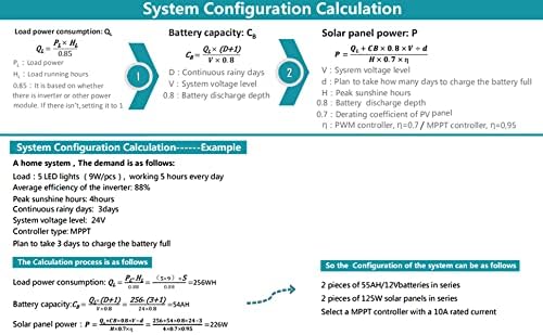
Image: An example of solar system configuration calculation, detailing formulas for load power consumption, battery capacity, and solar panel power, with a practical example for a home system.
9. Specifications
| Feature | Specification |
|---|---|
| Operating Temperature | 60 Degrees Celsius (Max) |
| UPC | 732376582445, 615150291712 |
| Manufacturer | EPEVER |
| Product Dimensions | 7.09 x 2.48 x 9.92 inches |
| Item Weight | 4 pounds (1.82 Kilograms) |
| ASIN | B07KW5W49J |
| Item Model Number | B07KW5W49J |
| Display Type | LCD |
| Max. PV Open Circuit Voltage | 100V (92V at 25℃ environment temperature) |
| PV Rated Charge Power (12V) | 520W |
| PV Rated Charge Power (24V) | 1040W |
| Rated Charge Current | 40A |
10. Troubleshooting
This section provides guidance for common issues. For complex problems, refer to the full product manual or contact customer support.
- No Display/Power: Check battery connections and voltage. Ensure the battery is connected first and has sufficient charge.
- No Charging: Verify PV panel connections and ensure sufficient sunlight. Check PV open circuit voltage.
- Incorrect Battery Type: Long press the 'ENTER' button on the battery voltage page to enter setting mode and select the correct battery type.
- Load Not Working: Check load connections, ensure the load is within the controller's rated capacity, and verify the selected load work mode.
- Over-current/Short-circuit Protection: The controller has built-in protections. If activated, disconnect the faulty component, resolve the issue, and reconnect.
11. Warranty and Support
The EPEVER 40A MPPT Solar Charge Controller comes with a manufacturer's warranty for 2 years from the date of purchase. For technical support, warranty claims, or further assistance, please contact EPEVER customer service or visit the official EPEVER store.
EPEVER Store: Visit the EPEVER Store on Amazon