
1. Introduction
This manual provides detailed instructions for the safe and effective operation of the BSIDE ADM30 5-in-1 Auto Range Multimeter. The ADM30 is a versatile digital multimeter designed for measuring various electrical and environmental parameters, including AC/DC voltage, AC/DC current, resistance, capacitance, frequency, duty cycle, noise level, luminance, humidity, and temperature. Please read this manual thoroughly before use and retain it for future reference.
Safety Information: Always observe general safety precautions when working with electrical equipment. Ensure the device is off before connecting or disconnecting test leads. Do not exceed the maximum input values specified for each function. Use appropriate personal protective equipment.
2. Product Overview and Features
The BSIDE ADM30 Multimeter combines multiple measurement capabilities into a single, compact device. Its key features include:
- Manual and Automatic Ranging: Allows for flexible and precise measurements.
- Relative Value Measurement: Displays the difference between the actual value and a set reference value.
- Large LCD with Backlight: Ensures clear visibility of readings in various lighting conditions.
- Auto Power-Off: Conserves battery life by automatically shutting down after 15 minutes of inactivity.
- Multi-functionality: Measures AC/DC Voltage, AC/DC Current, Resistance, Capacitance, Frequency, Duty Cycle, Noise, Luminance, Humidity, and Temperature.

Figure 2.1: Front view of the BSIDE ADM30 Multimeter, showing the display, function buttons, and rotary switch.
3. Setup
3.1 Battery Installation
The BSIDE ADM30 requires four 1.5V AA batteries (not included). To install the batteries:
- Ensure the multimeter is powered off.
- Locate the battery compartment cover on the back of the unit.
- Use a screwdriver to remove the screw securing the cover.
- Insert the four AA batteries, observing the correct polarity (+ and -) as indicated inside the compartment.
- Replace the battery compartment cover and secure it with the screw.
3.2 Connecting Test Leads
To connect the test leads:
- Insert the black test lead into the 'COM' (common) input jack.
- Insert the red test lead into the appropriate input jack for your measurement:
- For voltage, resistance, capacitance, frequency, temperature, humidity, noise, and luminance measurements, insert the red lead into the 'VΩHz%' jack.
- For current measurements up to 400mA, insert the red lead into the 'mA Temp' jack.
- For current measurements up to 10A, insert the red lead into the '10A MAX FUSED' jack.

Figure 3.1: The BSIDE ADM30 Multimeter shown with its included test leads and carrying case.
4. Operating Instructions
Turn the rotary switch to the desired function. Use the 'FUNCTION' button to cycle through sub-functions if available (e.g., AC/DC for voltage/current, different measurement modes).
4.1 DC/AC Voltage Measurement
To measure voltage:
- Set the rotary switch to the 'V' position.
- Press the 'FUNCTION' button to select between DC (direct current) and AC (alternating current) voltage.
- Connect the test leads in parallel to the circuit or component being measured.
- Read the voltage value on the display.

Figure 4.1: The multimeter displaying an AC voltage measurement from a power outlet.
4.2 DC/AC Current Measurement
To measure current:
- Set the rotary switch to the 'mA' or 'A' position depending on the expected current.
- Press the 'FUNCTION' button to select between DC and AC current.
- Connect the multimeter in series with the circuit. Ensure the circuit is de-energized before connecting.
- Apply power to the circuit and read the current value.
4.3 Resistance Measurement
To measure resistance:
- Set the rotary switch to the 'Ω' position.
- Ensure the circuit or component is de-energized.
- Connect the test leads across the component.
- Read the resistance value on the display.

Figure 4.2: The multimeter displaying a resistance measurement on a circuit board.
4.4 Capacitance Measurement
To measure capacitance:
- Set the rotary switch to the 'F' (Farad) position.
- Ensure the capacitor is fully discharged before connecting the test leads.
- Connect the test leads across the capacitor terminals.
- Read the capacitance value on the display.
4.5 Frequency and Duty Cycle Measurement
To measure frequency or duty cycle:
- Set the rotary switch to the 'Hz%' position.
- Press the 'FUNCTION' button to toggle between frequency (Hz) and duty cycle (%).
- Connect the test leads in parallel to the signal source.
- Read the frequency or duty cycle value on the display.

Figure 4.3: The multimeter displaying a frequency measurement.
4.6 Noise Level Measurement (dB)
To measure noise level:
- Set the rotary switch to the 'dB' position.
- Position the multimeter's microphone towards the sound source.
- Read the noise level in decibels (dB) on the display.
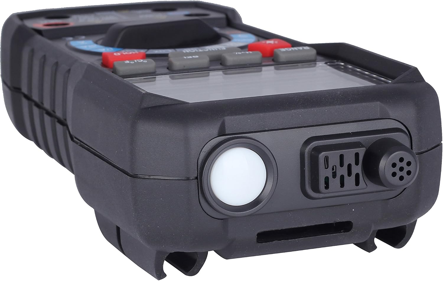
Figure 4.4: Side view of the multimeter, highlighting the integrated light and sound sensors.
4.7 Luminance Measurement (Lux)
To measure luminance:
- Set the rotary switch to the 'Lux' or 'x10 Lux' position.
- Point the multimeter's light sensor towards the light source.
- Read the luminance value in Lux on the display.

Figure 4.5: The multimeter displaying a luminance measurement in Lux.
4.8 Humidity Measurement (RH%)
To measure relative humidity:
- Set the rotary switch to the 'Temp' position. The display will show temperature and humidity simultaneously.
- Allow the sensor to stabilize in the environment.
- Read the relative humidity percentage (RH%) on the display.
4.9 Temperature Measurement
To measure temperature:
- Set the rotary switch to the 'Temp' position.
- Press the '°C/°F' button to switch between Celsius and Fahrenheit units.
- For ambient temperature, allow the internal sensor to stabilize. For external temperature, connect the K-type thermocouple (if included) to the 'mA Temp' and 'COM' jacks and place the probe at the measurement point.
- Read the temperature value on the display.
4.10 Other Functions
- RANGE Button: Manually select the measurement range or switch back to auto-ranging.
- REL Button: Activates relative value measurement mode.
- HOLD Button: Freezes the current reading on the display.
- Backlight Button (Sun icon): Toggles the display backlight on/off.
5. Maintenance
5.1 Cleaning
Wipe the multimeter casing with a damp cloth and mild detergent. Do not use abrasive cleaners or solvents. Ensure the device is powered off and disconnected from any circuits before cleaning.
5.2 Battery Replacement
Replace the batteries when the low battery indicator appears on the display. Refer to Section 3.1 for battery installation instructions. Always use new batteries of the specified type.
5.3 Storage
If the multimeter will not be used for an extended period, remove the batteries to prevent leakage. Store the device in a cool, dry place, away from direct sunlight and extreme temperatures.
6. Troubleshooting
- No Display: Check battery installation and ensure batteries are not depleted.
- Incorrect Readings: Verify that the correct function is selected, test leads are properly connected, and the measurement range is appropriate. Ensure the circuit is de-energized for resistance and capacitance measurements.
- 'OL' or 'OVER' on Display: Indicates an overload or out-of-range measurement. Select a higher range or ensure the input does not exceed the maximum specifications.
- Auto Power-Off: The device automatically turns off after 15 minutes of inactivity. Press any button or turn the rotary switch to power it back on.
7. Specifications
| Measurement Type | Range | Resolution |
|---|---|---|
| DC Voltage | 400mV / 4V / 40V / 400V / 1000V | 0.1mV / 0.001V / 0.01V / 0.1V / 1V |
| AC Voltage | 400mV / 4V / 40V / 400V / 750V | 0.1mV / 0.01V / 0.01V / 0.1V / 1V |
| DC Current | 400µA / 4000µA / 40mA / 400mA / 4A / 10A | 0.1µA / 1µA / 0.01mA / 0.1mA / 0.001A / 0.01A |
| AC Current | 400µA / 4000µA / 40mA / 400mA / 4A / 10A | 0.1µA / 1µA / 0.01mA / 0.1mA / 0.001A / 0.01A |
| Resistance | 400Ω / 4kΩ / 40kΩ / 400kΩ / 4MΩ / 40MΩ | 0.1Ω / 0.001kΩ / 0.01kΩ / 0.1kΩ / 0.001MΩ / 0.01MΩ |
| Capacitance | 40nF / 400nF / 4µF / 40µF / 100µF | 0.01nF / 0.1nF / 0.001µF / 0.01µF / 0.1µF |
| Frequency | 9.999Hz to 199.9kHz | 0.001Hz to 100Hz (range dependent) |
| Duty Cycle | 0.1% to 99.9% | 0.1% |
| Noise | 40-100dB | 0.1dB |
| Luminance | 4000 Lux / 40000 Lux | 1 Lux / 10 Lux |
| Humidity | 20-95% RH | 0.1% RH |
| Temperature (Internal) | 0~40°C / 32~104°F | 0.1°C / 0.1°F |
| Temperature (External) | -20~1000°C / -4~1832°F | 0.1°C / 0.1°F |
| Power Supply | 4 x 1.5V AA Battery (not included) | |
| Item Size | 19.5 x 9.5 x 6 cm | |
| Item Weight | 370g (without battery) | |
8. Package Contents
The standard package for the BSIDE ADM30 Multimeter includes:
- 1 x BSIDE ADM30 Auto Range Digital Multimeter
- 1 x Pair of Test Leads
- 1 x English Operation Manual (this document)
9. Warranty and Support
For warranty information and technical support, please refer to the documentation provided at the time of purchase or contact your retailer. Keep your purchase receipt as proof of purchase for any warranty claims.

